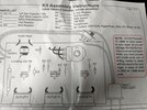
My son got a Chaney Electronics Color Organ kit for Christmas.
It has been assembled and he's attempting to use it and it doesn't quite work like we expected.
It has 3 channels. All three channels work. However we can't get all 3 to flash at the same time. If we adjust the stereo volume and the potentiometer so that one channel flashes, the other channels may not be on at all, or be on continually without flashing.
We are using LED christmas lights. Does this require incandescent bulbs? Any suggestions on how I can make this work as it should?
I guess we had the volume up too loud at one point because the transformer started smoking. Any chance that is part of our problem now? If so, anyone have a part number to purchase a new transformer?