Smartie
Member
Need help using a power supply unit [Solved]
Hey everyone,
I've begun work on reverse engineering a Epson Stylus C63 printer for my 3D printer project I want to build this year. It's been going pretty well so far. However, I now need to figure out how to enable/disable the power supply unit so I can use it for myself.
The power takes in 240V AC, outputs 42V and 5V.
The connector for the PCB has four pins on it, 42V, 5V, GND and PSC.
I'm guessing that the PCS is used for turning the unit on and off, however I can't get it to work myself
I've connected a 10KOhm resistor in series with a LED to 42V, and and 390Ohm in series with a LED to the 5V. I plugged in the power and the 42V LED lights up bright, but the 5V wasn't going, so I unplugged the power and let the unit discharge (the 42V LED slowly faded out). I then tried again with PSC grounded, this time the 42V LED was dim, un-grounding the PSC pin made the 42V LED go bright again after the the power was already removed.
I measured the voltages of the pins, 42V and GND measured 42V, PCS and GND measured 37V, while 5V and GND measures -3V and quickly dropped to -0.2V (consistent when testing multiple times).
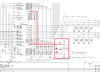
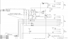
That's the best I can provide at the moment, Can you guys help me out in understanding this? I've posted the schematic for the power supply and the printer's main board below (the full schematic is on the last two pages of the service manual).
Cheers
Roman
Hey everyone,
I've begun work on reverse engineering a Epson Stylus C63 printer for my 3D printer project I want to build this year. It's been going pretty well so far. However, I now need to figure out how to enable/disable the power supply unit so I can use it for myself.
The power takes in 240V AC, outputs 42V and 5V.
The connector for the PCB has four pins on it, 42V, 5V, GND and PSC.
I'm guessing that the PCS is used for turning the unit on and off, however I can't get it to work myself
I've connected a 10KOhm resistor in series with a LED to 42V, and and 390Ohm in series with a LED to the 5V. I plugged in the power and the 42V LED lights up bright, but the 5V wasn't going, so I unplugged the power and let the unit discharge (the 42V LED slowly faded out). I then tried again with PSC grounded, this time the 42V LED was dim, un-grounding the PSC pin made the 42V LED go bright again after the the power was already removed.
I measured the voltages of the pins, 42V and GND measured 42V, PCS and GND measured 37V, while 5V and GND measures -3V and quickly dropped to -0.2V (consistent when testing multiple times).
That's the best I can provide at the moment, Can you guys help me out in understanding this? I've posted the schematic for the power supply and the printer's main board below (the full schematic is on the last two pages of the service manual).
Cheers
Roman
Attachments
Last edited: