A few things on this board as I'm trying to find if anything is shorted.. they seem to be all SOT parts.
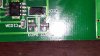
in the first pictures the parts that say M3A and M4A
The 2nd picture:
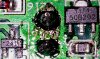
241 & 1114/50B202
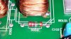
And the last one what is SG03?
in the first pictures the parts that say M3A and M4A
The 2nd picture:
241 & 1114/50B202
And the last one what is SG03?