Electro Tech is an online community (with over 170,000 members) who enjoy talking about and building electronic circuits, projects and gadgets. To participate you need to register. Registration is free. Click here to register now.
Welcome to our site! Electro Tech is an online community (with over 170,000 members) who enjoy talking about and building electronic circuits, projects and gadgets. To participate you need to register. Registration is free. Click here to register now.
Hi, can anyone help me to identify the values of L400 and L402 inductors on the Logitech Z-2300 motherboard? they are located near TDA amplifiers. Thanks in advance.
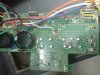
Well because I needed to replace a bad TDA7296 amplifier, but on the PCB there were lots of glue. While I tried to remove metal plate which pins all 4 of the TDA amplifiers to the radiator (which was also glued to the PCB) , I accidentally removed it with the glue and in it were two inductors.... so now I need to find their nominals so I could replace them...
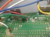
I can't see any components on your picture that look like inductors. It would have helped if you had said that this was an amplifier rather than describing it as a motherboard. I assume others (As I did.) assumed you were talking about a computer mother board.
Edit. After seeing Nigel's reply It looks like the option of fitting these components was not used. What is the fault an you equipment ?
Sorry if I have mistaken you, but you get my point now and that's what matters.
I had one faulty output channel (left speaker didn't work) and I have found one defective TDA7296 amplifier. In order to replace it I had to remove metal plate that I mentioned earlier. And that's how I have damaged these inductors
Exactly, this is a small toroidol inductor with ferrite core.
I think that these form a RLC low-pass filter. So the audio signal comes from dual operational amplifier (4565 IC) then passes the RLC low-pass filter and afterwards travels to TDA7296 amplifiers input. So if I would replace these small inductors with a peace of short wire, wouldn't the signal be distorted?
I can't see any components on your picture that look like inductors. It would have helped if you had said that this was an amplifier rather than describing it as a motherboard. I assume others (As I did.) assumed you were talking about a computer mother board.
Edit. After seeing Nigel's reply It looks like the option of fitting these components was not used. What is the fault an you equipment ?
Exactly, this is a small toroidol inductor with ferrite core.
I think that these form a RLC low-pass filter. So the audio signal comes from dual operational amplifier (4565 IC) then passes the RLC low-pass filter and afterwards travels to TDA7296 amplifiers input. So if I would replace these small inductors with a peace of short wire, wouldn't the signal be distorted?
No, there's no need for the inductors, as shown on the datasheet.
I would imagine they are there to help reject any strong RF signals (for if you live next door to a big transmitter), and FAR too low a value to affect audio in any way.
The Logitech Z-2300 speaker system has a subwoofer and two low power satellite speakers. The TDA7296 amplifier ICs drive the satellites with mid-range and high audio frequencies. Maybe the inductors are part of the crossover frequency dividing system (high-pass filters, not low-pass filters). Without a schematic we are just guessing. If the inductors are part of the crossover then removing them will cause low frequencies to destroy the tweeters.
The Logitech Z-2300 speaker system has a subwoofer and two low power satellite speakers. The TDA7296 amplifier ICs drive the satellites with mid-range and high audio frequencies. Maybe the inductors are part of the crossover frequency dividing system (high-pass filters, not low-pass filters). Without a schematic we are just guessing. If the inductors are part of the crossover then removing them will cause low frequencies to destroy the tweeters.
I have made audio equipment for radio stations. The RF fields are strong and cause strange things to happen in some audio amplifiers. I use ferrite beads to remove the RF. If this is the case then just short out the coil. (solder a piece of wire across the coil)
This site uses cookies to help personalise content, tailor your experience and to keep you logged in if you register.
By continuing to use this site, you are consenting to our use of cookies.

")