Continue to Site

Welcome to our site!

Electro Tech is an online community (with over 170,000 members) who enjoy talking about and building electronic circuits, projects and gadgets. To participate you need to register. Registration is free. Click here to register now.

  • Welcome to our site! Electro Tech is an online community (with over 170,000 members) who enjoy talking about and building electronic circuits, projects and gadgets. To participate you need to register. Registration is free. Click here to register now.

Need help on a circuit

Status
Not open for further replies.

1-3-2-4

Member
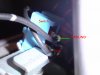
I have a LED dome light.. the other fixture it was in was from a newer car with 2 pins but my car only has one 12V and a screw to body ground.

Anyways the whole reason for me switching back was because one map light never worked which was the passenger side..

So I moved it back over to the fixture that came with the car however for some reason it's not working in the car.. So i took it inside and I'm puzzled.. I give 12 V to the wire and ground it out but when I press the switch to what should be turning on the light (light is already on) it shorts out the power supply.

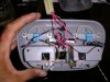
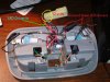
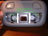
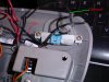
here is a picture of how it looks now
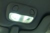
 

Attachments

  • DSC00354.JPG
    DSC00354.JPG
    416.8 KB · Views: 197
You are connecting 12 V to the red wire and Ground to the black wire, aren't you? That fitting looks as though it has both positive and negative wires, and does not use a body ground to the fitting.
 
What I don't get is why the light comes on when the switch is not pressed but the light turns off when it is (along with my power supply) because the protection kicks in when somethings shorts..

the funny thing is I get continuity with the switch pressed like any switch would but thats when the lights go off :-/
 
Last edited:
I think that you have managed to get the light and the switch in parallel.

That will happen if you apply power to the point where the switch connects to the light, and then you ground the other side of the light and the other side of the switch.
 
You need to disconnect the power feed from the common point where the switch connects to the lamp.

You need to connect the power to the other side of the switch from the common point.

It might help if you posted a photo that show the connections. In the photo, many of the wires are hidden, and where the power comes in is off the photo.
 
i hope this helps a bit more
 

Attachments

  • DSC00355.JPG
    DSC00355.JPG
    1,001.2 KB · Views: 132
  • DSC00356.JPG
    DSC00356.JPG
    635.5 KB · Views: 137
  • DSC00359.JPG
    DSC00359.JPG
    578.3 KB · Views: 143
Thanks for the photos.

I don't think that there should be any connection to the body ground. The power should be on the red wire(s) in the connector, and the ground should be on the black wire(s) in the connector.

The current path is:-
Red wire in from +ve of power connector to LED driver.
Black wire from LED driver to switch
Black wire from switch to negative of power connector

That's all. The circuit is duplicated, with one on each side of the housing. There is no connection though any screws to ground.
 
But.. here is where I'm confused in the old fixture I took this stuff out of it worked fine (at least just my side) the light would come on when I pressed the switch and went off when I pressed it again.. I on earth can't figure out what changed... I'm so close to thinking about swapping switches..
 
The switches are fine.

A faulty switch cannot short out a supply if it is correctly wired, because it should never be put in a position to where it can do that. A switch should either be open where no current flows, or a short circuit where the current is limited by the load.

A faulty switch may be open all the time, so the load never turns on.

It could be closed all the time where the load never turns off.

It could have some resistance where the load is not powered fully and the switch gets hot.
 
Thanks for the photos.

I don't think that there should be any connection to the body ground. The power should be on the red wire(s) in the connector, and the ground should be on the black wire(s) in the connector.

The current path is:-
Red wire in from +ve of power connector to LED driver.
Black wire from LED driver to switch
Black wire from switch to negative of power connector

That's all. The circuit is duplicated, with one on each side of the housing. There is no connection though any screws to ground.

it has a screw to ground but not using it at the moment that's the only way to power to fixture.. I'm not sure if you saw it but this type of fixture normally uses a festoon bulb so one end is to the switch and one end is to the silver bar which has a hole that screws into the roof of the car.. I will at some point have to make a connection to it but for the time being on the bench i'm just connecting the wire with a clip.

What i don't get is why does it do that when the switch is pressed? I think it should operate fine in Parallel since I have each LED on it's own driver.
 
In car circuits, the 12 V can be switched, or the ground can be switched. You have the red wires, which I think are the supply, connected directly to to the LED drivers. That means that the ground has to be switched.

However, if one side of the light is connected directly to ground, that means that the 12 V has to be switched. You maybe need to put the switches in the 12 V feed to the drivers.

yep thats what I needed to do! I have a question is it common for a lot of things to use a switched ground?

*edit man a problem! If I tie it into the 12V if I turn on one light the other comes on

*edit 2

fixed it
 
Last edited:
yep thats what I needed to do! I have a question is it common for a lot of things to use a switched ground?

Yes, it is quite common. Car interior lights is one place where switched ground it used, because the wiring to the door switches is simpler that way.

Many semiconductor switched devices are arranged to switch the ground, because NPN transistors and N-mosfets are usually slightly higher performance that the equivalent PNP or P-mosfets.

Not of course forgetting traditional contact breaker ignition systems that switch the ground connection.

I'm glad you got the light to work.
 
Status
Not open for further replies.

Latest threads

New Articles From Microcontroller Tips

Back
Top