Continue to Site

Welcome to our site!

Electro Tech is an online community (with over 170,000 members) who enjoy talking about and building electronic circuits, projects and gadgets. To participate you need to register. Registration is free. Click here to register now.

  • Welcome to our site! Electro Tech is an online community (with over 170,000 members) who enjoy talking about and building electronic circuits, projects and gadgets. To participate you need to register. Registration is free. Click here to register now.

need help in programming pic16f628a

Status
Not open for further replies.

chantal

New Member
hello,

i am working on my final year project which is connecting a movement sensor to the pc using the serial port....
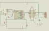
i had help concerning the schematic and how to connect the movement sensor to the pc.
i am using max232,pic16f28a, movement sensor and a contverter usb to serial since on my laptop there is no serial port...

now the problem i am facing is that i need to program the pic16f628a to be able to recieve its output on my pc.
to be more clear, the movement sensor will detect the presence of a person standing in front of it and will close the contact so what i need to do is to recieve the output given by this sensor on my pc so i will know that it has detected...

any help will be appreciated.

thx

P.S: i need the pic16f628a code in assembly,since i already know this language and if u can also send me the schematic in isis i would be greatefull...
thx again
 
Last edited:
good point...it's just that i am a newbee in assembly coding...i have been reading tutorials and so on...but still need some ideas..so if u can help i would appreciate it but if you can't .....then stop wasting my time
 
good point...it's just that i am a newbee in assembly coding...i have been reading tutorials and so on...but still need some ideas..so if u can help i would appreciate it but if you can't .....then stop wasting my time

For starters, you need to leave the attitude at home, or somewhere else...just not here. ;-)

Generally, members are more than willing to help, once you have shown what you have done by yourself and indicated points which you don't understand.

Please remember, people contributing to this, or any other forum, do so in their own free time without any financial incentive.
 
Please post what you have so far.

You can attach schematics using the 'Go Advanced' button, then selecting 'Manage Attachments'. From there, you can upload PDF & image files from your PC and attach them to your posts.

If you are adding code to a post, make sure to highlight the entire code and click the # icon....this will add the CODE tags and keep the proper formatting.

Regards.
 
Chantal, first thing I would do is get the USB-serial device working. Connect it up and loop the TX and RX at the serial end and try it out in Hyperterminal.

Then get the PIC and MAX232 wired up. Blink an LED first, to make sure the PIC is running. Diagrams abound via Google for the PIC-to-MAX232 wiring connections.

When you've got it all wired together, you'll need serial routines for the PIC. Check Nigel's tutorials (see the forum Sticky), or piclist.com, or Google...there are tons of examples, really, in any language you want.

So post what you have and let's see where you're having trouble.
 
here is my schematic and the code i am using....

plz note that in my schematic instead of using a movement sensor i used a switch...since i couldn't find a sensor in ISIS.
and i think it is correct because the sensor when detecting will close its contact, so what i am doing is when the switch closes i need to send a signal to the pc...
if there any clarifications plz ask me..
thx a lot for your help...

PS : the code written is meant to test UART...when trying to run on ISIS i keep getting this error "no model specified for J1 " (the DB9 female) i have no clue what this means.
 

Attachments

  • schematic..jpg
    schematic..jpg
    208.9 KB · Views: 310
  • 628uart..asm
    3.4 KB · Views: 165
Last edited:
here is my schematic and the code i am using....

plz note that in my schematic instead of using a movement sensor i used a switch...since i couldn't find a sensor in ISIS.
and i think it is correct because the sensor when detecting will close its contact, so what i am doing is when the switch closes i need to send a signal to the pc...
if there any clarifications plz ask me..
thx a lot for your help...

PS : the code written is meant to test UART...when trying to run on ISIS i keep getting this error "no model specified for J1 " (the DB9 female) i have no clue what this means.

hi chantal,
Tried your asm in Oshonsoft, it runs fine.
Ref the image.

AAesp08..gif
 
Please post what you have so far.

You can attach schematics using the 'Go Advanced' button, then selecting 'Manage Attachments'. From there, you can upload PDF & image files from your PC and attach them to your posts.

If you are adding code to a post, make sure to highlight the entire code and click the # icon....this will add the CODE tags and keep the proper formatting.

Regards.

i have posted my schematic and the assembly code
thx
 
Chantal, first thing I would do is get the USB-serial device working. Connect it up and loop the TX and RX at the serial end and try it out in Hyperterminal.

Then get the PIC and MAX232 wired up. Blink an LED first, to make sure the PIC is running. Diagrams abound via Google for the PIC-to-MAX232 wiring connections.

When you've got it all wired together, you'll need serial routines for the PIC. Check Nigel's tutorials (see the forum Sticky), or piclist.com, or Google...there are tons of examples, really, in any language you want.

So post what you have and let's see where you're having trouble.

i have posted the schematic and the assembly code....i need to modify the code in a way that as long as the button is pressed i will be able to recieve a msg (for example on or anything else) on my pc. in other words i want to keep recieving "on" untill i release the button....is this doable?
thx for ur help and ur time
 
Regarding your ISIS issue, click on J1 and select "Exclude from simulation" from the check box list.

Regarding your original issue, if you need to detect just one sensor, you can (if your particular chip has the feature, and I am 99% sure it does) use RB0/INT to pick up on the interrupt, which will "interrupt" your code and process the button / sensor state immediately.
 
Status
Not open for further replies.

Latest threads

New Articles From Microcontroller Tips

Back
Top