Electro Tech is an online community (with over 170,000 members) who enjoy talking about and building electronic circuits, projects and gadgets. To participate you need to register. Registration is free. Click here to register now.
Welcome to our site! Electro Tech is an online community (with over 170,000 members) who enjoy talking about and building electronic circuits, projects and gadgets. To participate you need to register. Registration is free. Click here to register now.
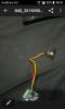
It could possibly have 5pins instead of just the three.should I assume that the 2extra pins at the back are just for stability or are they like an on/off deal like on the one below or is the one belows on/off function seperate from the 3main pins? With the one below if you labelled the pins 1-5 with one being the most left going counter clockwise and the 3main pins being 2,3&4 you would run the positive thru 1 out 5 then to either 2 or 4 with 3going to the motor+ right?
In the above post I'm assuming that the pot I took the foto of works the same as the possibly 5pin pot on the Pwm circuit board above.if I'm incorrect and should just bridge the 2back pins then let me know.
Excellent. thanks for your help debe and everyone else I think I got it from here.will come back here(electrotechonline) from now on for all electrical enquiries.
This site uses cookies to help personalise content, tailor your experience and to keep you logged in if you register.
By continuing to use this site, you are consenting to our use of cookies.