Continue to Site

Welcome to our site!

Electro Tech is an online community (with over 170,000 members) who enjoy talking about and building electronic circuits, projects and gadgets. To participate you need to register. Registration is free. Click here to register now.

  • Welcome to our site! Electro Tech is an online community (with over 170,000 members) who enjoy talking about and building electronic circuits, projects and gadgets. To participate you need to register. Registration is free. Click here to register now.

need help.. frequency to voltage converter using PIC

Status
Not open for further replies.

natasya

New Member
my project is frequency to voltage converter using PIC.
but i dont know suitable PIC for my project..
i am also dont know how to complete this project..

the project is to read input frequency and give the output in voltage..

for example like below..

input (hz) / output (v)
100 / 0.1
200 / 0.2
300 / 0.3

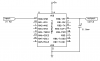
can i use 16f887a or 16f873??
i hope you all can help me..
thanks to all..
 
there a easy way to do this and it works with any pic you check for frequency say on porta,0

Then output a voltage on portb using it as voltage divider like in the pic
 

Attachments

  • like_this.png
    like_this.png
    21.2 KB · Views: 771
there a easy way to do this and it works with any pic you check for frequency say on porta,0

Then output a voltage on portb using it as voltage divider like in the pic

To be a little clearer, it's an R2R DAC - not just a 'voltage divider'. It's also pretty essential to feed it through a high impedance buffer, unless the load is already a high impedance.
 
Nigel I'm not as smart as you I don't know whats it proper name but it works i used with the stamp. This gives greater details
 
There's an easier way to do it. Everytime an input pulse / edge is detected you just get the PIC to make a fixed-period output pulse. Then average the output pulses into an RC filter.

So if you want 100Hz = 0.1v (ie 1000Hz = 1v)
just generate a 1000Hz/5 output pulse. Or 200uS.

The benefit of this is that you can use the very bottom end PICs for it, like 10F or 12C series.
 
thanks all...

actually i dont want use voltage divider...

can i use the output in PWM and convert it to voltage???


MR RB, can yo explain in more detail what was you wrote here??

Thanks..
 
thanks all...

actually i dont want use voltage divider...

can i use the output in PWM and convert it to voltage???


MR RB, can yo explain in more detail what was you wrote here??

Thanks..

It's an R2R DAC - not just a 'voltage divider'
And you have the idea you test for 100hz then send a higher 1000hz
which would give you 1 volt peak put a 10uf cap on it and it will look like 1 volt
 
Last edited:
Something like this would work your testing for 100hz if a 100 hz in you send back out a 1khz which with a filter capacitor looks like 1 volt
If you want .1 volt send a 10khz out
 

Attachments

  • likethis.png
    likethis.png
    21.3 KB · Views: 676
Last edited:
thanks all...

actually i dont want use voltage divider...

can i use the output in PWM and convert it to voltage???
MR RB, can yo explain in more detail what was you wrote here??

Thanks..

What I suggested is that you program the PIC to send out a fixed length pulse, every time it detects an input pulse. Then the PIC output pin goes into a RC filter of 1 resistor and 1 cap.

The beenfits are that it is very simple, you onlt need a simple PIC (no ADC or DAC or timers needed) and it has infinite resolution, which is impossible to get with a R2R DAC or any 8bit DAC.
 
This is all the help you should need. The code goes something like this;

Code:
 ; Super simple freq - voltage converter. RomanBlack Oct 2009
 ; connect input to PIC pin RA0
 ; connect output RC filter from PIC pin RB0
 ; 200uS delay means 1000Hz input = 1v DC output
 start

 btfsc PORTA.0 ; first wait for input to be low
 goto $-1

 btfss PORTA.0 ; now wait for input to go high
 goto $-1

 bsf PORTB.0  ; set output high
 nop ; enough nop's here to make 200uS delay
 nop ; or use your own 200uS delay code
 nop ; (etc)
 bcf PORTB.0  ; set output low again

 goto start
 
It works like this It don't work. All he posted was how to get 1 volt by pulsing RB0 at 1000hz
You still need to cheak for 100 hz 200 hz and so on.

Which means you have a little more then this
Code:
btfsc PORTA.0 ; first wait for input to be low
 goto $-1

 btfss PORTA.0 ; now wait for input to go high
 goto $-1
this will not tell you if it was 10 100 or 1000hz all it will do is give you 1 volt on RB0 if RA0 is high
 
Have a think again. :)

The system I posted makes exactly one output pulse for every input pulse. Zero error and infinite resolution.

The 200uS output pulse is always the same period, again zero error.

It will make 0.1v for 100Hz, 0.3v for 300Hz, 1v for 1000Hz etc just as the OP asked.
 
RB what you posted just scales PORTA,0 by 10 and outputs on PORTB,0
PORTA,0 = 100hz then PORTB,0 scales to 1000hz the code you posted will do that.
 
Last edited:
thanks all...
i think i has understand it..
can you give the value for R&C and how to calculate the delay and output voltage..
for example, the PWM amplitude is 10 volts.
high delay is 99uS and low delay is 1us will give approximately 10 volt.
if high is 90 and low is 10, how to calculate the voltage output??

is it i was understood??
 
Status
Not open for further replies.

Latest threads

New Articles From Microcontroller Tips

Back
Top