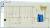
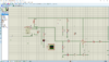
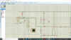
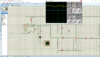
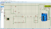
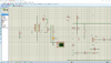
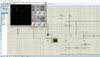
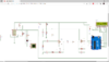
Hello, I am working on a vehicle speed detection system using the hb100 doppler radar sensor. I am simulating on proteus first before I start the construction process, i couldn't find the library of the hb100 sensor to add unto proteus, so i made use of an astable circuit to act as the HB100 sensor. I also added an led and an oscilloscope to display output of the astable circuit, which is also connected to the amplifier circuit. I found a code to use, but I noticed that when I connect my astable cct output to the amplifier cct the LCD display is empty(No output shown). However on connecting my astable cct directly to the Arduino digital pin 8 my frequency and speed are displayed. The questions i need to ask are.
1. Why is my output not displaying when I connect my astable cct to the amplifier cct.
2. I want to make modification to the code to display "Ovr Spd" when the speed is above 50km/hr and "Norm Spd" when speed is equal and less than 50km/hr.
Screenshot 78-82 are with amplifier cct and no output display.
Screenshot 83-85 are without amplifier cct and output display.
screenshot 86 is a clear view of the amplifier cct.
Note: I recently changed my 5v battery to 9v to test something.
I am new to coding and cct design. I will appreciate all the help I can get. Thanks
Attachments
-
 Screenshot (78).png140.4 KB · Views: 1,527
 -
 Screenshot (79).png140.5 KB · Views: 1,033
 -
 Screenshot (80).png119.3 KB · Views: 916
 -
 Screenshot (81).png180.7 KB · Views: 859
 -
 Screenshot (82).png234.4 KB · Views: 943
 -
 Screenshot (83).png140.3 KB · Views: 955
 -
 Screenshot (84).png119.1 KB · Views: 962
 -
 Screenshot (85).png224 KB · Views: 908
 -
 Screenshot (86).png139.7 KB · Views: 1,344
