Electro Tech is an online community (with over 170,000 members) who enjoy talking about and building electronic circuits, projects and gadgets. To participate you need to register. Registration is free. Click here to register now.
Welcome to our site! Electro Tech is an online community (with over 170,000 members) who enjoy talking about and building electronic circuits, projects and gadgets. To participate you need to register. Registration is free. Click here to register now.
want to be cheapest.actually i used .47uf cap then four diodes then 12v zenor and 47uf/16v capacitor.but if i shake the power supply plug sometimes the zenor fuses.
OK, I will give you a simple schematic, which I tested with low current IC's like UM3482,UM3484,UM66,UM3561,UM3562,NE555,LM741 & LM556.
It ulilises R1 as a series droper.D1 rectifies the voltage obtained through R2,while D2 stabilises the output to the specified voltage. C1 filters the output.This is capable of supplying 25mA current and almost any voltage ranging from 3-24V by selecting suitable components for R2,D2 & C1, even if the input Ac voltage varies from say,195-270V.The output is sufficiently regulated.
The current supplying capability can be increased to about 40-50mA by using a 5.6K,20W resistor as R2,but this would require the use of at least a 1W zener.You may select the output from the following table.
For 3V output, R2=15K,D2=3V & C1=220uf
For 6V output, R2=12K,D2=6.2V & C1=220uf
For 9V output, R2=10K,D2=9V & C1=220uf
For 12V output,R2=10K,D2=12V & C1=470uf
For 15V output,R2=10K,D2=15V & C1=470uf
For 18V output,R2=10K,D2=18V & C1=1000uf
For 24V output, R2=8.2K,D2=24V & C1=1000uf
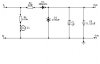
Ravi's circuit contain a half-wawe rectifier with one diode.The disadvantage only a high power dissipation on 10k resistor. (must be a wirewound type) See this circuit with bridge (full-wawe) rectifier and a serial condenser. The output current about 10..15mA, enough for low-power CMOS circuits. The condenser must be X2 type, 275VAC rating.
Here isn't heat dissipation (very low).
first thing the size of the 10w resistor in Mr ravi's model. is very big when compared with the timer board.also using a resistor always produces more heat.
is ur model ok .i used a 1k 2w resistor and it produces heat .as i am a beginer please tell me what is theVOLT for 100n cap and what watts 1k rsistor. also what is x2 type condenser .our current voltage is 230v.so help me with values.
As i wrote the condenser voltage 275V AC. The X2 type condenser designed for continous AC application as filter cap. The 1k resistor only protect against in-rush current, value not critical: between 470ohm...1k and 0.1W.
This site uses cookies to help personalise content, tailor your experience and to keep you logged in if you register.
By continuing to use this site, you are consenting to our use of cookies.

")