trennonix
New Member
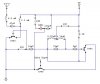
here i tried to reproduce the schematics of a 27Mhz transmitter
can you guys plz check if my reproduction is correct (i know you don't have the transmitter in front of you, just say if it can work or not)
and how can i amp it up? can i simply replace the transistors with bigger ones? and maybe up the voltage?
the two inductors (0.22 and 0.78) add up to 1uH which is in parallel with a
33pF capacitor thus 27.72Mhz
the inductor is a specially made one so i had to count the loops and do some imprecise measuring to figure its value
thanks
")
