Continue to Site

Welcome to our site!

Electro Tech is an online community (with over 170,000 members) who enjoy talking about and building electronic circuits, projects and gadgets. To participate you need to register. Registration is free. Click here to register now.

  • Welcome to our site! Electro Tech is an online community (with over 170,000 members) who enjoy talking about and building electronic circuits, projects and gadgets. To participate you need to register. Registration is free. Click here to register now.

Mysterious Problem!

Status
Not open for further replies.

matasoft

New Member
When I power on the PIC, sometimes (not always!!!) it does things that
I didn't programed it to do.
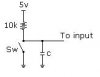
I have built this keyboard controller (see the image) and I programed
it to output ASCII code through PORTB.
I put LEDS to PORTB through resistors to see the output.
When there is a false DATA, RA3 sets.
An example of the program:

1) START BUTTON CHECK. IF RA2 = 0 THEN CONTINUE.
1) GET DATA.
2) IF THERES A PROBLEM IN TRANSFER, SET RA3.

Well, the problem is that when I power up the PIC it sets RA3 before I
switch the button. I power off and power on again and it does another
things like lighting various LEDS.

HOW THIS HAPPENS!!!??!!
:evil: :evil: :evil: :evil:
I don't know if anyone have a solution about this problem! I have tried
to solve it adding various electronic parts but I failed.
I have this same problem in every circuit that I create.

SORRY, for the bad English.
 

Attachments

  • circuit_163.jpg
    circuit_163.jpg
    22.9 KB · Views: 1,018
To help you we need information.
like what are u using to get the program into the pic with( Software & hardware)
which chip is it?

lastly,if u could post the pic assembly program somone might be able to help.
 
Sorry, I forget! I' m using a PIC16F84A and I upload the program using the software IC-PROG with the hardware JDM Programer. I wrote the program to MPLAB.
I'm sure that the program works very well because I simulated it many times.
I'll post the program tomorrow!

Thanks for your reply. :wink:
 
What are you using as power supply? What is voltage and is it filtered and regulated?
 
Perhaps the I/O pins are not initialized properly.
Make sure you set the direction and output value in the beginning of the program.
 
matasoft said:
When I power on the PIC, sometimes (not always!!!) it does things that
I didn't programed it to do.
.

What have you done with MCLR ?
 
Well, It's better to start from the Beginning:

I have a problem with PICs and I don't know how to solve it.
When I power up the PIC, sometimes it outputs data that I didn't programmed it to or it jumps a piece of code without to execute it. For example, when I create a button Loop and you have to push the button for the program to continue, it continues without to push the button.
To fix this problem I have to Power off and Power on the circuit a couple of times to have a normal operation. I have this problem in all PIC circuits that I created. The Power supply I use hasn't got a problem because I have used and an another power supply that I have, even and an ATX Power Supply but the problems continue. The PIC works fine because, I have used another two and I have the same problems.
I even added some capacitors on the output of the Power Supply and on the I/O pins of the PIC to see if the problem is fixed, but nothing.
Below I have a Test Circuit that I have built and its code.
Please, someone build this curcuit!! because I'm going MAD and I don't know what TO DO!!!
Switch the Button of the power supply a couple of times to see if you have the same problem. I have built this circuit on a Breadboard and I don't use the power supply button to Power on-off because I have to wait every time I power off for the power supply capacitor to discharge before I can power on again. I simply connect and disconnect the +5V cable from the Breadboard.
I have written this code in MPLAB and I upload the code to the PIC using the software IC-Prog with the JDM Programmer.
I'm using a PIC16F84A with the following settings:
Oscillator = XT
Watchdog Timer = Disabled
Power Up Timer = Enabled
Code Protection = Disabled


Heres the Code:
#include "P16F84A.INC"

ORG 0
;INITIALIZATION
BSF STATUS, RP0
MOVLW B'00000001'
MOVWF TRISB
BCF STATUS, RP0

BUTTON:
BTFSC PORTB, 0
GOTO BUTTON
MOVLW 0FF
MOVWF PORTB
LOOP:
GOTO LOOP

END
 

Attachments

  • circuit_237.jpg
    circuit_237.jpg
    89.5 KB · Views: 813
matasoft where are the equates in the assember program?
they need to be defined.
and some comments in the program would be nice also. :D
 
It doesn't need to define PIC's special purpose registers, I just call the library PIC16F84A.INC and have them autodefined!
That's why I put the code line #include "P16F84A.INC".
It's a simple code, it just checks if the button is pushed and then lights all the Leds that connected in PORTB, that's why I didn't put comments in the code.
 
Just a couple of points:

1) You don't show an HT decoupling capacitor on the circuit, you should have one close to the PIC - the one in the PSU is too far away - this could easily use problems.

2) Your pull-up resistor is rather low, 470 ohms is needed, try putting a couple of zero's on the end - 47K would be better. But this shouldn't have any bearing on your problem.

3) Using a breadboard! - I'm not very impressed with breadboards, particularly when you using a 4MHz oscillator on it.

You might try looking at my tutorials, they use the 16F628 (the replacement for the old 16F84A), but you can easily use the 84 for those that don't require the extra I/O or facilities.
 
My advice :
Has you should knew your pic port will burn if the load is more than 25mA (30mA when out=0) TOTAL or let me explain better if you have all led's On the consumption will be of abouth 74mA :lol: your Pic is probablly heating a lot, take care of it or you will need to purchanse another, try using another resistor value above 1.5k for each led, for the led try Red Low Consumption since you are driving them directly, as Nigel said a Cap is needed in parallel with the pic source even if the source is regulated ( the other components than the Pc will generate interfearences this Cap supresses them! )
The best thing you could do is to check on your Pic DataSheet there are code examples to learn and common Pic power circuit and oscilator options.
Bla bla bla!
 
I think I know what the problem is.
You are not clearing the input and output latches on the ports. Even though you set the data direction with the TRISB correctly, you are not removing the status of the pins that was there the last time the program ran. This is why you're noticing that when you turn it off for a while, and turn it on, it runs correctly as any charges have been discharged. But if you turn it off and back on quickly, it runs incorrectly. It's using past ghost values.

Try this:

Code:
org 0x000             ; Program reset vector (Start location)
;Initialization
bcf STATUS, RP0       ; Memory Bank 0
clrf PORTA            ; Clear data latches on Port A
clrf PORTB            ; Clear data latches on Port B
bsf STATUS, RP0       ; Memory Bank 1
movlw  b'00000001'    ; B0 as input, all others output
movwf TRISB           ; Set data direction
bcf STATUS, RP0       ; Memory Bank 0

Even in the simplest programs, commenting is godly. :)

Another thing that could be giving you some trouble is that your switches/buttons are bouncing. They're electromechanical devices, and they are not perfect. Whenever you push them, they don't instantly change from not connected to connected right away. There's a bit of wobble. The solution is to use a small capacitor across the switch pins. This is called debouncing. Below are images of the voltage level the PIC sees with a button or switch that is not debounced, and one that is.
 

Attachments

  • switch_636.jpg
    switch_636.jpg
    2.9 KB · Views: 672
  • switch_noise.jpg
    switch_noise.jpg
    3 KB · Views: 678
  • switch_cap.jpg
    switch_cap.jpg
    2.6 KB · Views: 679
TiagoSilva, you are incorrect. You said, "you should knew your pic port will burn if the load is more than 25mA (30mA when out=0) TOTAL".

Actually, if you look at the PIC data sheet, in the electrical characteristics data section, it lists the following:

Maximum current sourced by PORT A: 50mA (all 5 on at same time)
Maximum current sourced by PORT B: 100mA (all 8 together)
Maximum current sourced by any I/O pin: 25mA (individual basis)

Assuming a 1.8 volt drop across the LEDs he is lighting, and that he is using a 5 volt source,
(5v - 1.8v) / 470 ohms = 6.8mA per pin
It would be 6.8mA * 7 = 47.6mA total for Port B powering 7 LEDs as in the schematic above. He could actually decrease those resistors to make the LEDs brighter and still be well within acceptable limits.

8)
 
Well, I learned many things from you all!!!
Thanks for your help, I'll try to do what you said and write to you again.
:lol: :lol: :lol: :lol: 8)
 
I finally managed to solve the problem!!!
:D
I simply write the following code lines at the beginning of the code as bonxer said:
CLRF PORTA
CLRF PORTB

I thank you all for your help!
Your time isn't wasted because I'm going to use what I've learned from you.
:wink:
 
matasoft said:
I finally managed to solve the problem!!!
:D
I simply write the following code lines at the beginning of the code as bonxer said:
CLRF PORTA
CLRF PORTB

I thank you all for your help!
Your time isn't wasted because I'm going to use what I've learned from you.
:wink:
i think we all learned something here . :D i know i did .
since i am just learning pic assembler , every little bit helps.
no pun intended :D
 
Status
Not open for further replies.

Latest threads

New Articles From Microcontroller Tips

Back
Top