silentsnow
New Member
Since I have no money to fabricate PCB, I have to go to school components store and collect them. My friend Terrence help me a lot, who gave me 18F4550. For others components, I have to buy them from market.
The test result: all pass, including debugging and downloading.
Before this ICD2, I tried "The simplest ICD2", but it failed under MPLAB 7.42.
In addition, the Vpp has some problem: it can not pull MCLR down to ground, (MCLR is pulled-up to Vcc with 10K resistor in the circuit.)
It only spend me 9 Singapore Dollar (around 5.6 US dollar).
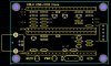
Here is my pictures:
**broken link removed**
**broken link removed**
schematic + firmware, based on 16F877A/16F877 and 18F4550:
http://yangzetao.googlepages.com/877and4550USB.rar
Or you goto the original Website:
http://www.icd2clone.com/wiki/Main_Page
")
----------Chinese Characters Bellow----------
因为自己没有资金去做PCB。
于是,自己就从学校里面拿了很多元器件,然后朋友Terrence帮忙给了18F4550,其他少的东西就去买了.
测试结果是:一切顺利,除了Vpp有点问题,可能这和设计有关吧。
如果看不到图片,就看看这里:
呵呵
http://yangzetao.googlepages.com/myIcd2.jpg
http://yangzetao.googlepages.com/myIcd2-YT.jpg
电路图+固件,基于16F877A/16F877和18F4550
http://yangzetao.googlepages.com/877and4550USB.rar
网站原址:
http://www.icd2clone.com/wiki/Main_Page
赞一个!
The test result: all pass, including debugging and downloading.
Before this ICD2, I tried "The simplest ICD2", but it failed under MPLAB 7.42.
In addition, the Vpp has some problem: it can not pull MCLR down to ground, (MCLR is pulled-up to Vcc with 10K resistor in the circuit.)
It only spend me 9 Singapore Dollar (around 5.6 US dollar).
Here is my pictures:
**broken link removed**
**broken link removed**
schematic + firmware, based on 16F877A/16F877 and 18F4550:
http://yangzetao.googlepages.com/877and4550USB.rar
Or you goto the original Website:
http://www.icd2clone.com/wiki/Main_Page
----------Chinese Characters Bellow----------
因为自己没有资金去做PCB。
于是,自己就从学校里面拿了很多元器件,然后朋友Terrence帮忙给了18F4550,其他少的东西就去买了.
测试结果是:一切顺利,除了Vpp有点问题,可能这和设计有关吧。
如果看不到图片,就看看这里:
呵呵
http://yangzetao.googlepages.com/myIcd2.jpg
http://yangzetao.googlepages.com/myIcd2-YT.jpg
电路图+固件,基于16F877A/16F877和18F4550
http://yangzetao.googlepages.com/877and4550USB.rar
网站原址:
http://www.icd2clone.com/wiki/Main_Page
赞一个!