Continue to Site

Welcome to our site!

Electro Tech is an online community (with over 170,000 members) who enjoy talking about and building electronic circuits, projects and gadgets. To participate you need to register. Registration is free. Click here to register now.

  • Welcome to our site! Electro Tech is an online community (with over 170,000 members) who enjoy talking about and building electronic circuits, projects and gadgets. To participate you need to register. Registration is free. Click here to register now.

My DIY CDPlayer "from scratch "

Status
Not open for further replies.

ZERS

New Member
Hi,
I attend to share this experience with all of you.
I've started to build my own CDplayer.

-It is based on the CDPRO2 mechanism of https://www.daisy-laser.com.
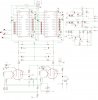
-I do not use the internal DAC of this unit, but I built a DAC with 2 TDA1541A in //,. The protocol of incoming digital data from the unit is I2S
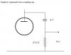
The DAC is using the 6C45PI vaccum tube as output buffer.

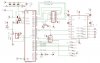
- The controller is based on the PIC18F452. There is a LCD (4-Bits programmed), buttons, IR and DSA interfaces. The DSA protocol is used to receive/send data from the CDPRO2 unit. (take a look at the CDPRO2 datasheet)

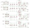
- I built as well as PSU board as I need several voltages :
+5V for the DAC, controller, unit
-5V, -15V for the DAC
9V for the unit.

I didn't completed the PSU for the output buffer so far, let's be patient :wink:

You will find enclosed some schematics and boards.

The schematic of the controller board is still a "draft" as there remains several task to do, for example, dealing with the ON/OFF sequence of the CDplayer.

Tell me what do you think about htis project
 

Attachments

  • schemapsu.jpg
    schemapsu.jpg
    139.9 KB · Views: 1,439
  • schemacontroller_880.jpg
    schemacontroller_880.jpg
    100.9 KB · Views: 1,486
Hi ZERS,

don't like the look of C 20 and C 22,
are those values correct ?

I assume this unit is to drive a further
tube output unit.

Best of luck with it, John :)
 
Looks quite impressive.
I don't have the time to check for any errors, but it seems you've put quite some time into it...

Keep up the good work and keep us informed about the progress...
especially the pic code would be interesting.
 
Had another look,
still not happy about the 4.7 mfd caps.

Maybe they are supposed to be coupling caps.

John :)
 

Attachments

  • 4.7_cap.jpg
    4.7_cap.jpg
    10 KB · Views: 1,222
I agree, john1. In the original schematic the anode voltage sitting on the output...
And the plate voltage... why 235V? The datasheet say max 150V.
 
Sebi said:
I agree, john1. In the original schematic the anode voltage sitting on the output...
And the plate voltage... why 235V? The datasheet say max 150V.

I agree as well, the capacitors are drawn in the wrong place, they should be output coupling capacitors. The anode load resistors seem uncommonly low as well, usually these would be much higher - as you say the anode voltage is likely to be too high with those values, I would normally expect to see 100K-470K as anode loads on triodes.

However, the whole idea of adding a couple of pointless valves to a CD player seems strange? - I find the current fad for adding pointless valves really strange, but as least these are wired in circuit!.
 
Sebi said:
I agree, john1. In the original schematic the anode voltage sitting on the output...
And the plate voltage... why 235V? The datasheet say max 150V.
You all have right guys , I had posted a "old" schematic but not the up-to-date one...

I deleted the schematic as well as its board from the previous post, but I should have problem with my NET supplier, as I can no longer attach files... As soon as I try, my internet session is crashing :evil:

Will try later... :roll:

As far as the 235V is concerned, the datasheet explains that the tube is class A "polarized" in the middle of its linear curve. So it consums current... After figuring out some electric rules, I found 235V, voltage that I have seen as well in other DIY projects using those vaccum tubes.

Sorry my english isn't good, I could not clearly explain you why 235V, but be sure that this is the correct voltage, as well as the 4K7 5W resistor :p
Regards
 
new try :lol:
 

Attachments

  • schemadac.jpg
    schemadac.jpg
    265.2 KB · Views: 1,193
  • cartedac.jpg
    cartedac.jpg
    225.2 KB · Views: 1,191
Hi Zers, Exo, Sebi, Nigel,

Thanks for the support, i always feel a bit 'unsure' when trying
to second guess someone elses design.
It seems that the drawings posted were 'early' ones, later ones
had the capacitors 20 and 22 shown correctly.

Still, i spose it shows we're not asleep ...

As to the anode loads (resistors), yes i thought them a bit low
too, but ive seen lower in places, and didn't clock it.
However i looked up a bit on that valve, its a B7G base with an
anode plate that must be less than a square cm each side, so i
do agree with Nigel on that, those values are suspiciously low,
or maybe they might be intended for supply voltages in the area
of sixty or seventy volts.
I suggest posting the details of that valve for perusal, or the
URL to the details. All i found was a picture of it.

I am guessing that the main purpose of this adaptation is to
drive a valve output section to the speakers.

Extensive tests were done some years ago based on so many people
claiming that valves 'sound' better. For myself, my hearing is
not critical enough to distinguish. After much carrying on and
getting many people involved, the outcome of these tests (from
electronics weekly i think) finally decided that where the signal
transferred from unit-to-unit and especially between sound-to-
signal (mic) and between signal-to-sound (speakers) then the use
of valves made a difference, but they made no indication of what
that difference might be, other than 'noticeable'
They concluded that within a circuit there seemed to be no
difference whether the amplifying is done with transistors or
valves (assuming similar signal to noise ratios)

Based on the above, maybe this is why a CD player is being put
together in this way. For the purpose of driving a valve output
amp.

If thats not the case, then yes - it seems rather pointless.

Regards, John :)
 
Ça veut dire...

inutile, vain.

Buena suerte (bonne chance, n'est ce pas?)

Agustín Tomás
 
Re: Ça veut dire...

atferrari said:
inutile, vain.

Buena suerte (bonne chance, n'est ce pas?)

Agustín Tomás
merci pour tout.
Je suis francais même si j'ai un nom espagnol :wink:
 
john1 said:
Based on the above, maybe this is why a CD player is being put
together in this way. For the purpose of driving a valve output
amp.

If thats not the case, then yes - it seems rather pointless.

Regards, John :)
As now I understand the word "pointless", I do not understand why you explained that this is pointless to have an output buffer made of tubes if the amplifier is made of transistors....

Some amplifiers like the Zenquito or other JM Plantefeve amplifiers are made of transistors, but they sound like "tube".

Moreover, i guess it is better to use vaccum tubes as buffer if one day, I want to build a tube amplifier...

Regards
 
D'un but a l'autre

C'est la 1ere fois que l'on rencontre un projet qui va des tubes au micro.

Merveille! Tu trouves pas un chose comme ça tous les jours.

Bonne chance.

Agustín Tomás
 
En fait, j'ai des larges bandes en stock (fostex) que je compte driver plus tard avec un ampli à tube 2*20W.

Mais pour le moment j'ai "qu"'un ampli à transistors DIY aussi qui marche très bien.
J'ai pas envie (et les moyens financiers) de changer pour le moment.

A+

In english :
Actually, I've got some full range drivers (fostex) that I plan to drive with a 2*20w class a tube amplifier later.

But for the moment, I've "only" have a transistor amplifier that sounds nice. I do not have enough money to start this new amplifier

Cheers :wink:
 
Status
Not open for further replies.

New Articles From Microcontroller Tips

Back
Top