Continue to Site

Welcome to our site!

Electro Tech is an online community (with over 170,000 members) who enjoy talking about and building electronic circuits, projects and gadgets. To participate you need to register. Registration is free. Click here to register now.

  • Welcome to our site! Electro Tech is an online community (with over 170,000 members) who enjoy talking about and building electronic circuits, projects and gadgets. To participate you need to register. Registration is free. Click here to register now.

must be a better way to control LEDs

Status
Not open for further replies.

MrDEB

Well-Known Member
SETUP= using two contacts in a door . When door opens, the contacts open then the 5 LEDs come ON
AND the PWM circuit shuts OFF
thinking just add an NPN to control the PWM circuit.
will draw up a better diagram if need be but somehow this circuit I posted dosn't look right or stable??
 

Attachments

  • door circuit..PNG
    door circuit..PNG
    28.6 KB · Views: 271
Depends on your criterion for "better". if you want simpler, just have the door switch apply power to the LEDs or shunt the LEDs so they see no current.
 
maybe this will be a better description

door layout and schematic but only have two wires in door but can maybe use the door hinge as third conductor then maybe chariplex the LEDs in the door as the other two windows have 4 wires but can I use PWM controlling 3 LEDs with ONLY 3 wires? need to think on this but suggestions welcome.
this is for a tabernacle I am building for a friend/parishioner.
SETUP - two stationary stained glass windows and one stained glass window in the door.
Behind the windows are three LEDs that flicker using a PIC/PWM.
The ceiling or top inside of tabernacle has 5 bright LEDs with 470 ohm resistors on each (all wired together in parallel see schematic)
when door is opened the inside LEDs come on
The window LEDs come on when the photo transistor "sees dark"
 

Attachments

  • door circuit con&#116.PNG
    door circuit con&#116.PNG
    113.7 KB · Views: 212
  • candle windows..PNG
    candle windows..PNG
    35.7 KB · Views: 148
charlexplexing leds

hope I got this right. Charilexplexing LEDs using PWM
will try out after scouts tonight. handing out pinewood derby awards
 

Attachments

  • led candles..PNG
    led candles..PNG
    38.4 KB · Views: 152
Your description is much better now. Which LEDs are part of the door assembly and which parts are not on the door? (I suspect the three you are multiplexing are on the door, but am checking).
 
In my latest schematic I show 9 LEDs that are charliplexed. Dosn't really matter (?) as long as I have three. Thinking one from each groupe of three.
In the schematic I have window 1, window2 and door marked on the LEDs.
Slight change - may have to ADD a micro switch to the door lock to control the 5 cluster LEDs as the door contacts are used to power the door LEDs.
Still concemplating
 
Got it programed into Junebug BUT!

only get LED1 and LED2 to light up (referring to Junebug layout)
need to reconfigure something??
had to change from portB to portA for Junebug chariplexing since this is basically what I want to do is have 3 LEDs for each candle (2 blue and one clear for each window)
any suggestions??
Code:
Device = 18F1320
Clock = 8

Include "IntOSC8.bas" 
Include "RandGen.bas"
Include "Utils.bas" 
Dim TMR2IE As PIE1.1,         // TMR2 interrupt enable
    TMR2IF As PIR1.1,         // TMR2 overflow flag
    TMR2ON As T2CON.2,        // Enables TMR2 to begin incrementing
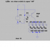
    Signal_Pin As PORTb.0     // Signal output to frequency meter
 
Dim Red_Pin As PORTa.0,        //was b.0
    Green_Pin As PORTa.6,       //was b1
    Blue_Pin As PORTa.7,        //was b2
    Red_Duty As Byte,
    Green_Duty As Byte,
    Blue_Duty As Byte,
    Red_DutyVal As Byte,
    Green_DutyVal As Byte,
    Blue_DutyVal As Byte,
    RandomVal As Byte
   
 
Dim uS As Word,
    mS As Word           
   // ranval(1)as word
Interrupt TMR2_Interrupt()
    High(Signal_Pin)
    Save(0)                   // Back up system variables   
    If TMR2IF = 1 Then        // Check if the interrupt was from TMR2   
        TMR2IF = 0            // Clear the TMR2 interrupt flag
        uS = uS + 50
        If uS >= 1000 Then
            uS = uS - 1000
            Inc(mS)
        EndIf       
        Inc(Red_DutyVal)
        Inc(Green_DutyVal)
        Inc(Blue_DutyVal)
        If Red_DutyVal > Red_Duty Or Red_Duty = 0 Then
            Red_Pin = 0
        Else
            Red_Pin = 1
        EndIf
        If Green_DutyVal > Green_Duty Or Green_Duty = 0 Then
            Green_Pin = 0
        Else
            Green_Pin = 1
        EndIf
        If Blue_DutyVal > Blue_Duty Or Blue_Duty = 0 Then
            Blue_Pin = 0
        Else
            Blue_Pin = 1
        EndIf               
    EndIf                     //
    Restore                   // Restore system variables
    Low(Signal_Pin)
End Interrupt
 
Private Sub TMR2_Initialize()
    TMR2ON = 0                // Disable TMR2
    TMR2IE = 0                // Turn off TMR2 interrupts   
 
    PR2 = 149                 // TMR2 Period register PR2
    T2CON = %00000001         // T2CON 0:1 = Prescale
                              //        00 = Prescale is 1:1
                              //        01 = Prescale is 1:4
                              //        1x = Prescale is 1:16                                 
                              //      3:6 = Postscale              
                              //     0000 = 1:1 postscale
                              //     0001 = 1:2 postscale
                              //     0010 = 1:3 postscale...
                              //     1111 = 1:16 postscale
 
    TMR2 = 0                  // Reset TMR2 Value   
    TMR2IE = 1                // Enable TMR2 interrupts
    TMR2ON = 1                // Enable TMR2 to increment
    Enable(TMR2_Interrupt)
End Sub
 
// Start Of Program...
Low(Red_Pin)
Low(Green_Pin)
Low(Blue_Pin)
Red_Duty = 30
Green_Duty = 0
Blue_Duty = 0
Red_DutyVal = 0
Green_DutyVal = 0
Blue_DutyVal =0
 
uS = 0
mS = 0

RandGen.Initialize(128)       // Initialize the Random Number generator
TMR2_Initialize               // Setup and enable TMR2
 
While True                    // Create an infinite loop
    RandomVal = RandGen.Rand  // Grab a random number from 0 to 255 
    // Select RandomVal         // Find out what colour to increase/decrease
        //Case 0 To 42
             Red_Duty =RandomVal-5 
                //mS = 0
             // (Red_Duty)=Rand(1)
               // Repeat
               // Until mS = 19
               // and Red_Duty>0
           // endif
           
            
        //Case 43 To 84
            If Red_Duty > 0
              Then  mS = 0
                Repeat
                Until mS = 19
                Dec(Red_Duty)
            EndIf
       // Case 84 To 127
             Green_Duty =RandomVal-20 
              //Then  mS = 0
              //  Repeat
              //  Until mS = 19
              //  Inc(Green_Duty)
           // EndIf
       // Case 128 To 170
            If Green_Duty > 0
              Then  mS = 0
                Repeat
                Until mS = 19
                Dec(Green_Duty)
            EndIf
      //  Case 170 To 212
             Blue_Duty = RandomVal-30
             // Then  mS = 0
              //  Repeat
              //  Until mS = 19
              //  Inc(Blue_Duty)
           // EndIf
       // Case 212 To 255
            If Blue_Duty > 0
              Then  mS = 0
                Repeat
                Until mS = 19
                Dec(Blue_Duty)
            EndIf
            Wend
          
         End
 
Status
Not open for further replies.

Latest threads

New Articles From Microcontroller Tips

Back
Top