Continue to Site

Welcome to our site!

Electro Tech is an online community (with over 170,000 members) who enjoy talking about and building electronic circuits, projects and gadgets. To participate you need to register. Registration is free. Click here to register now.

  • Welcome to our site! Electro Tech is an online community (with over 170,000 members) who enjoy talking about and building electronic circuits, projects and gadgets. To participate you need to register. Registration is free. Click here to register now.

Musings: DIY Electronic ignition to replace magneto.

Status
Not open for further replies.

3v0

Coop Build Coordinator
Forum Supporter
Just after posting this I found a project base of an 16F PIC that may be what I want http://www.molla.org/DIY-CDI/. You may still find the discussion interesting. Or maybe not.

I have been making progress on my road roller restoration. The carb and fuel system in general have been refreshed but I have no spark!

I should add that I hooked a neon bulb in series with a 2K resistor and it would flash but not near enough juice for the sparkplug.
The motor is wisconsin AENLD and I have obtained a 2nd one and it is acting just like the one on the road roller. The first vid is of a nice AENLD restoration.


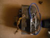
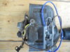
The engines have what is called an impulse magneto. I will talk about the state of the magneto after I discuss the electronic ignition proposal.


A really great invention in its time, but the repair parts are outrageous, about $40 x 2 for just points and condensor, much more if the coil is bad or there is mechanical wear that needs fixing. It is not an easy device to debug. Also suffers from the same mechanical problems all point based systems have. Note that with this magneto there is no magnet on the flywheel.

It has me thinking that maybe it is time to create an electronic ignition system for it. Given that the roller uses a 12V starter using a magneto is sort of pointless. Most systems use a magnet on the flywheel and hall effect sensor. I could do that but I would have to lighten the flywheel on one side then attach a magnet to it. If one did this I expect one could use a much smaller magnet then used for flywheel based magnetos. Rather then do that I am thinking of using a bit of reflective tape and a sensors that has the LED light source and the phototransistor in the same case. I am aware that the sensor would best be shielded from ambient light. Obviously we will have to not use IR.

People who know me are already guessing that I will be wanting to use a PIC. Advantages of doing so are the addition of timing advance and rev limiter. The AENLD is a fairly long stroke and should not exceed 3600 RPM.

The current setup has a fixed spark advance of 20 degrees BTDC. I am tempted to put the foil closer or even at TDC and fire the plug there for starting. As revs pick up it would use a bit of math and maybe the counter timers to adjust the timing to 20 degrees BTDC.

I want to search the web a bit and see what I want to do on the high voltage side.

About the magneto. I have the points and condenser out of the 2nd engine. The points look bad but I might be able to clean them up. At first I did not trust the condenser. I need to bring it in the house and test it with the mondo superprobe. Now I am suspect of the coils. The one I have apart reads as an open circuit but I think I read someplace they are hard to test and this may be due to inductance??

I do hope I can get a magneto working so I can get this project rolling. Pun intended.
 
Last edited:
If you decide to use CD, which works well with both 2-cycle and 4 -cycle engines, let us know. There are several threads on hobby sites for systems, and I have a lot of additional files. The major problem: you will need a battery.

Thus, in this application, I would not scrap using a magneto. Perhaps an Echo or other cheap weedeater magneto can be adapted. Used weedeaters are often free, because the motor blows or the cheap rotary carb gives up.

John

PS: I vaguely recall seeing pointless magneto modifications. I have focused my interests on CD because of weight in aircraft.
 
Be advised that magnetos have an "impulse coupling" for starting. Energy is stored in a spring, and the magnet is mechanically snapped past the coil pole-piece at a much faster rate than would happen due to the slow rotation of the engine while starting. The impulse coupler also retards the spark timing during starting, to minimize kick-back. I know this game from timing aircraft magnetos...

Hard starting is symptomatic of a failed impulse coupler.
 
John
The roller has a 12V delco starter/gererator combo so it already has a car battery. Physically it looks like a delco generator but it has a starter winding on the same armature. I imagine they used the magneto setup because it would work even if the generator and/or battery failed.

Mike,
I am aware of the impulse coupling. There is some disagreement as to if this magneto has altered timing for starting. It is a FMXDIB7U

I am going to do my best to cleanup the points and put the magneto back together tomorrow. Even if I go the electronic ignition route I would like to have the magneto around for historical reasons or if I even opt to sell it. People might not be to hip to have a DIY ignition.

General

Good news is that the carb on the 2nd ANEL engine I got from my neighbor has a really clean looking carb from the outside. By that I mean it has not been worked on by apes mechanics.

Found a news group for DIY CD ignitions https://groups.yahoo.com/neo/groups/DIY-CDI/conversations/messages
Not sure if that link will work unless you are registered but that is the group. Lots of catching up to do.
 
I had a Case 444 that had the same setup. I had forgotten that detail. Let us know if you want a bunch of links for CD. A conversion should not be that difficult.

John
 
Here is some CDI stuff from the hobby world. If you want more, go to RC Universe and search on "CDI DIY". You will get about 17 threads. These threads seem to develop a life of their own, become many pages quickly, and are hard to follow. RCGroups has a whole section on DIY electronics, including ignitions.

If you want just one thread, this is where I would go. Jake Stewart is the engine behind it:
https://www.rcgroups.com/forums/showthread.php?t=1781959

Here are some older threads by most of the same authors. The key workers are Gompy (aka Bigboat), Nyemi (mostly programming) and Jake Stewart (jakestew) who seems to have the patience of Job.
https://www.rcuniverse.com/forum/engine-conversions-92/9842658-complete-new-cdi-website-open.html
https://www.rcuniverse.com/forum/engine-conversions-92/10662258-cdi-gr8flyer55.html
https://www.rcuniverse.com/forum/en...6-new-cdi-opensource-project-jmj-bigboat.html
https://www.rcuniverse.com/forum/engine-conversions-92/9842658-complete-new-cdi-website-open.html

Here are schematics for the current versions of the 12F1840 and 12F508a ignitions:
10.16.13.PNG

One other thing, there is a lot of discussion about advance, retard, and timing curves. These guys are trying to reach 9000+ rpm. From my understanding, those issues are relatively unimportant in a single cylinder engine like you have.

John
 
Last edited by a moderator:
I have started in on the first thread. I was a little concerned about the current and voltage needed for a old wisconsin vrs the little model engines but it seems they are using this on motorbikes so it should work for me too.

Thanks much John.
 
Maybe a dumb question(probably a dumb question?), but why reinvent the wheel? Why not use one of the many schemes on this site or the web that uses a OEM (Ford or GM) ignition module to drive the coil? They can be used with points, even worn out points to trigger the modules.

As far as timing advance and rev limiter, can't ever remember seeing advance on a small engine like this, and rev limit is done by the governor and carb.
 
I do not have access to junkyard parts and want a circuit I can easily replicate.

I would just as soon have the rev limit on the ignition too. Should there be a mechanical problem it will keep the engine from self destructing.

I am currently looking at purpose built ignition ICs. One is mentioned in my roller thread.
 
I have several Wisconsin AENL and AENLD series engines at home so I'm fairly familiar with both their starting and ignition systems.

RPM wise I would not worry about over revving being I have seen them where they have lost their governor linkages and have revved up to the point valve float limits their speed (4200 - 4800 RPM) without ever throwing a rod or worse. By todays common small engine standards they are very robustly overbuilt.

Points and condenser wise most any newer condenser from any other ignition system works well enough in those magnetos. They are by no means fussy about how well matched the capacitance is. Anything close is good enough.

Points wise one common cheat I have seen is simply cutting the end off the old points and silver soldering the ends from a common cheapo set on to rebuild the stock ones.

The other thing is to just use a common 12 volt ignition coil and use the points inside the magneto to trigger it. Personally I find that the most easy conversion to work with.

The other more involved cheat for putting modern ignition on them is to simply take the ignition coil system off of a Tecumseh or other similar small engine that has the ignition coil mounted inside the flywheel and just imbed a small set of neodymium magnets into the flywheel and make a simple bracket to hold the coil assy.
 
  • Like
Reactions: 3v0
Some simple options I like that too.

Are the contacts made using silver solder to start with so you have nice flat matting surfaces to work with? Take off the old and put on the new sort of thing with no real fitting.
 
Another alternative if the coil is still good in the magneto. Use either an Atom IGN module or NOVA 11 IGN modules to replace the points & condencer. The picture is a Lucas SR magneto with a copy of an Atom module on it.
 

Attachments

  • SR LUCAS MAG.1.JPG
    SR LUCAS MAG.1.JPG
    1.6 MB · Views: 1,041
  • SR LUCAS MAG.3.JPG
    SR LUCAS MAG.3.JPG
    1.5 MB · Views: 943
Are the contacts made using silver solder to start with so you have nice flat matting surfaces to work with? Take off the old and put on the new sort of thing with no real fitting.

It depends on what ones you have. Some are sort of riveted or swaged in place while others just have the contacts silver soldered at their base.

The ones that are silver soldered are easy to replace/transplant and in many cases over sized contacts from a large electrical relay or contactor or even an old mechanical voltage regulator could be put in their place and then file fit for best alignment.
 
  • Like
Reactions: 3v0
Status
Not open for further replies.

Latest threads

Back
Top