Continue to Site

Welcome to our site!

Electro Tech is an online community (with over 170,000 members) who enjoy talking about and building electronic circuits, projects and gadgets. To participate you need to register. Registration is free. Click here to register now.

  • Welcome to our site! Electro Tech is an online community (with over 170,000 members) who enjoy talking about and building electronic circuits, projects and gadgets. To participate you need to register. Registration is free. Click here to register now.

Multisim and 7447

Status
Not open for further replies.

hbkhalil

New Member
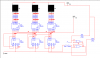
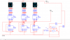
Hi , i m trying to build a 3 digit counter using 7447 and BCD/7 seg CA.
I have a littel problem with BI/RB0 and BI , I have to link BI/RBO and RI to Vcc other wise it wont work, but I need BI and RBO to eliminate the insignificant 0 , how can i do that ??
Please help me.
Thank you for reading my post and for ur future answers.
 

Attachments

  • Capture1 .PNG
    Capture1 .PNG
    25.5 KB · Views: 2,365
  • Capture2.PNG
    Capture2.PNG
    26.5 KB · Views: 467
Hi,

From the datasheet: "by grounding the RBI of the highest order decoder and connecting its BI/RBO to RBI of the next lowest order decoder, etc., leading zeros will be suppressed. Similarly, by grounding RBI of the lowest order decoder and connecting its BI/RBO to RBI of the next highest order decoder, etc., trailing zeros will be suppressed."

"Leading and trailing zeros can be suppressed simultaneously by using external gates, i.e.: by driving RBI of a intermediate decoder from an OR gate whose inputs are BI/RBO of the next highest and lowest order decoders."

LT should be held high.
 
Last edited:
Thank you for you answer , i did exacly what you said , but i still have the same problem , i think that there is a problem with multisim.
Capture3.PNG
This is what i get

I can send you the multisim file if it can help.
Thx again
 
Last edited:
Hi,

On your schematic, I see no RBI that is grounded. So if you did what the datasheet states, your schematic doesn't show it. On your schematic, the RBI at U10 is held high, for example; not grounded. There could be a problem with the simulation, but I don't have multisim.
 
Last edited:
I tryed to ground it , but i have the same probleme .
I tryied to test the 7447 with this shematic , and it doens't work unlesse RBI/RB0 in hight , it is supposed to be an output !!!, i don't understandCapture4.PNG
 
RBI/RB0 can be either an input or an output. As an output, it is an open collector output that can be forced low.
 
Last edited:
I didn't know that , thx for the info.
But when i realised the shematic i linked RBO to a prob and it worked and didn't in multisim , i had to link it to Vcc .
 
Unfortunately, simulations often do not fully model a device. Particularly, an all digital simulation may not simulate an open collector output properly. Maybe try linking that pin to VCC through a resistor, if possible.
 
Last edited:
Yes it s the only way , but we can't eliminate the insignificant zeros.
Thank you so much for ur help , i guess that i should find a new simulator :)
 
Your welcome. If it's any consolation, just from curiosity, I tried a freeware simulation (CircuitMaker) of the 74LS47 and the RBO pin outputs PULSES when RBI is grounded and the BCD data is zero. So much for that simulation.
 
Last edited:
Status
Not open for further replies.

Latest threads

New Articles From Microcontroller Tips

Back
Top