Continue to Site

Welcome to our site!

Electro Tech is an online community (with over 170,000 members) who enjoy talking about and building electronic circuits, projects and gadgets. To participate you need to register. Registration is free. Click here to register now.

  • Welcome to our site! Electro Tech is an online community (with over 170,000 members) who enjoy talking about and building electronic circuits, projects and gadgets. To participate you need to register. Registration is free. Click here to register now.

Multiplexing array of strain gauge

Status
Not open for further replies.

nickagian

Member
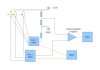
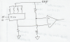
I intend to use a single A/D channel with one InAmp and one Wheatstone bridge in quarter-configuration at its input as AFE for an array of multiple strain gauges with nominal resistance of 1kΩ. Obviously, this needs to be implemented with a multiplexer (only solid-state solution is acceptable). However, I am concerned of the error that will be introduced by the on-resistance of the MUX. Do you think that this issue is important? As far as I have seen in the market, the lowest on-resistance that can be selected is 300mΩ.
 
Your most important requirement is not how low the multiplexer resistance is, but how well matched are the respective channels of the multiplexer.
 
The impedance of the MUX is always in portion to the impedance of the input pin. If the InAmp has 300,000 ohms of impedance, the error will be 1/10th of 1%.

Got it?
 
Your most important requirement is not how low the multiplexer resistance is, but how well matched are the respective channels of the multiplexer.
And why is this requirement so important?

The impedance of the MUX is always in portion to the impedance of the input pin. If the InAmp has 300,000 ohms of impedance, the error will be 1/10th of 1%.

Got it?
Well, I admit that I do not understand what you mean. Isn't the impedance of the MUX stable? The datasheet says that the ron is at most 0.3Ω for example. It doesn't say that the value of this resistance is in portion to something else. But anyway, the strain gauges will be connected with a three-wire configuration in a quarter-bridge. Thus, two MUX are needed, as seen in the figure below. For the one that connects the measuring cable to the InAmp I agree, that the error is quite small. But the second MUX in fact changes the impedance of the left arm of the bridge.
 

Attachments

  • multiplexing_SG.jpg
    multiplexing_SG.jpg
    77.4 KB · Views: 387
Last edited:
How about you post a schematic so we all know which configuration we're talking about?

You have right, sorry for that. I had already posted the schematic by the time that you posted your own words, so you couldn't possibly see it.
 
Why do you need two muxes?

Let me rephrase the requirement. Make the mux resistance small compared to the source resistance of the strain gauge. Make sure all of the channels of the mux have well matched ON resistance.
 
Why do you need two muxes?

Let me rephrase the requirement. Make the mux resistance small compared to the source resistance of the strain gauge. Make sure all of the channels of the mux have well matched ON resistance.

Regarding your first question, please have a look at the schematic that I have posted. Is that completely wrong? Regarding the rest of your answer, I just cannot understand why well matched ON resistance between the channels of the MUX is so important. But anyway, I will pay attention to this when choosing the device.
 
Here is what I was thinking:
 

Attachments

  • SG.png
    SG.png
    382.4 KB · Views: 387
Here is what I was thinking:

Yes, I have understood this. But the other connection (with 3 wires for each strain gauge) is better if the sensors are to be placed in some distance from the measuring point, which is what is happening in my case.
 
If you want to minimize the effect of the switch resistance controlling the voltage to the strain gage, you could use a constant current source in place of the 3.3V constant voltage source. That would provide a constant current to the strain gauge bridge, independent of the switch resistance. You just select the constant current value to generate the desired voltage across the bridge resistance.
 
I am going to assume you plan to use foil type strain gauges for your application. Now generally speaking my experience using foil type gauges is that they really don't lend themselves well to being multiplexed. The following quote is taken from here.

1.3.3 Advantages and Disadvantages of Foil Strain Gauges

An advantage of the foil strain gauge is that it is mass-produced making it cheap, reliable, and relatively small. Also, the workings of the foil strain gauge are simple yet accurate. The resolution of a foil strain gauge is 0.1 μstrain with a maximum strain of 200,000 μstrain. The inherent temperature compensation of the Wheatstone bridge adds to the advantages of the foil strain gauge system. The foil strain gauge also has very little transverse sensitivity compared to wire strain gauges, because the large amounts of area at the turns on the foil gauge prevent perpendicular strains from affecting the performance.

A disadvantage of foil strain gauges is their inability to be multiplexed. Each sensor is attached to its own conditioning equipment and in order to get data from multiple spots, a dedicated system is needed for each one. Also, because the strain gauges are electrical they are susceptible to electromagnetic interference.

Mounting the sensors is also a problem. The test piece must be sanded and washed with great attention to detail as no to contaminate the epoxy. For accurate measurements the gauge must be fixed to the test piece very securely and as close as possible, which means using a clamp to get a very thin and uniform amount of epoxy. Finally the lead wires must be soldered in place, cleaned of excess flux, and a protective coating applied. With some practice these tasks can be mastered for a simple laboratory test piece, however if the test piece is not readily accessible or removable some of the tasks can be nearly impossible.

The epoxy itself can also be a problem because of curing temperatures and times. Also the epoxy is not a perfectly elastic material. The sensors can undergo creep, which is a gradual lowering of the strain that acts on the gauge. Creep can occur due to a bad bond, or from steady or highly repetitive strain. Higher operating temperatures can also weaken the epoxy and cause creep if special high temperature epoxy is not used.

For highly precise measurements hysteresis is another disadvantage of foil strain gauges. Hysteresis is when a high amount of strain is applied and then released from the strain gauge. The gauge will seem deformed and will have a higher resistance value at zero strain than initially. A similar effect will happen in the opposite direction and setting up a hysteresis loop. The loop can be narrowed to negligible values by repeatedly stressing the gauge in opposite directions. However, A typical value of error is 0.1 percent and usually can be ignored for measurements less than 1500 microstrain. A plot of a hysterisis loop is shown in Figure 1.5.

What is the mV/V output of your bridge to be? I ask because with only 3.3 volts excitation your actual output will be very, very low per unit of measurement. Even when using a 3 or 4 wire excitation configuration. Using 3 or 4 wire excitation will only ensure the excitation voltage at the bridge(s) is maintained and accurate and then only for a specific bridge. If I read right on that note.

Since each gauge has so many variables my best success with a setup like this is for each gauge to have its own instrumentation amplifier (signal conditioning) to allow for individual calibration. I am just not very keen on multiplexing the outputs of each gauge to a single instrumentation amplifier. However, your call as I don't know what uncertainty you need. Again, this is just my thoughts on the subject.

Ron
 
hi Ron,
This has also been my experience that its important to have a IA for each strain gauge bridge.
Strain gauges of the same type do have slightly different characteristics of span and offset, which need a conditioning amplifier before a multiplexer.
 
Last edited:
Upon further thought, if using "half bridge" foil gauges which have two arms, then using a single fixed gain instrumentation amp (where the gain/offset is set to span the offsets of the individual gauges will work). You can store the correction for the gain/offsets for each gauge and correct after the data is acquired.

Putting a single multiplexer between the center tap of the gauge and the input node of the instrumentation amp will minimize the offsets due to the ON resistance of the mulitiplexer transistors because the current flow is just the input bias current of the instrumentation amp, which will be tiny...
 
Last edited:
Thank you all for your really helpful replies!

In fact, I decided to go without multiplexer at the beginning, because this seems to be the most 'clean' and accurate solution (although it includes a larger BOM and more cost). If during design I find out that so many InAmps do not fit on the pre-fixed dimensions of the PCB I intend to construct, then I will try to use a multiplexing solution.
 
Status
Not open for further replies.

Latest threads

Back
Top