Continue to Site

Welcome to our site!

Electro Tech is an online community (with over 170,000 members) who enjoy talking about and building electronic circuits, projects and gadgets. To participate you need to register. Registration is free. Click here to register now.

  • Welcome to our site! Electro Tech is an online community (with over 170,000 members) who enjoy talking about and building electronic circuits, projects and gadgets. To participate you need to register. Registration is free. Click here to register now.

Move switch from guitar fx pedalboard to external switch

Status
Not open for further replies.

RedW

New Member
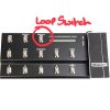
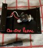
Hi, I have a Line 6 FBV MkII shortboard that has a number of footswitches to control the various patches. One of them turns a looper on and off but it is in a really difficult position to use so I’d like to move it to an external switch.

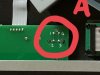
The switch is a 6mm tactile - This one.

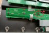
Would it be possible to solder a wire to the existing solder points under the switch and then to the underside of a new switch in an external unit?

Thanks for your help.

Pete
 
That should work ok. Make sure there is also good mechanical support for the cable ends, to provide strain relief, as someone is sure to trip over the cable :).
 
Thanks, if I understand the wiring, I should be able to take the new internal wires to a new jack lead socket and then do the reverse on the new switch. I plan to use an existing switch that uses a similar mechanism for example - Footswitch, although I realise I might need to re wire the new pedal.

Does that sound right? Any help with making sure I understand the wiring correctly would also help.

Thanks
 
Good news, I was struggling with the sketch! I’ll pull something together tomorrow and post it.

Thanks for the help.
 
So here are some photos to hopefully show what I want to do.

1 - Pedalboard is the outside of the pedalboard with the Loop switch highlighted.
2- The inside of the board with the reverse of the tactile switch highlighted
3 - The tactile switch turned over. You can also see the reverse of the individual switch that activates it
4 - The simple on off switch
5 - Enlarged image of the reverse of the tactile switch.

So my theory was that I could somehow solder wires to the reverse of the switch then to a jack socket that I could plug the on off switch into. Failing that, hard wire the new wires from the switch directly to the on-off switch.

If this is possible, i will need to understand which pints on the switch go to the 2 parts of a jack socket.

Thanks!
 

Attachments

  • 1 - Pedal Board.jpg
    1 - Pedal Board.jpg
    46.9 KB · Views: 113
  • 2 - Pedal Board reverse.jpg
    2 - Pedal Board reverse.jpg
    1,007.4 KB · Views: 112
  • 3 - Tactile switch.jpg
    3 - Tactile switch.jpg
    828.7 KB · Views: 112
  • 4 - On-Off switch.jpg
    4 - On-Off switch.jpg
    842.6 KB · Views: 104
  • 5 - Switch rev large.jpg
    5 - Switch rev large.jpg
    53.6 KB · Views: 105
Not all tact switches have the same pinout, so you would need to identify (with no power on the pedal board), using a multimeter set to a low Ohms range or set for a continuity test, which two pins get bridged when the switch is pressed.
It would probably be two diagonally opposite pins.
 
Thanks for the reply. If I work out which pins are which, how do i understand how they map to a jack plug? I'd definitely rather not hardwire it.
 
Unless the jack plug has an external voltage source connected (which it shouldn't, because there should only be a foot-switch connected) you can treat the two pins as non-polarised.
 
Thanks. Does that mean that as long as I identify the 2 pairs of bridged pins I can join them and solder them to either point of the jack socket?
 
Yes, although there may be only one pair. On some tact switches two of the pins are used only to provide mechanical support.
 
Status
Not open for further replies.

Latest threads

New Articles From Microcontroller Tips

Back
Top