Continue to Site

Welcome to our site!

Electro Tech is an online community (with over 170,000 members) who enjoy talking about and building electronic circuits, projects and gadgets. To participate you need to register. Registration is free. Click here to register now.

  • Welcome to our site! Electro Tech is an online community (with over 170,000 members) who enjoy talking about and building electronic circuits, projects and gadgets. To participate you need to register. Registration is free. Click here to register now.

motorised valve control

Status
Not open for further replies.

tonymoo

New Member
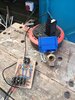
A 12vdc 2w motorised valve needs to have its input wires polarity reversed to open and close the valve according to whether there is power being supplied to another component in the system (which is not directly connected electrically to this valve)


In other words, when the separate component is switched on, this valve needs to be open and when the separate component is switched off this valve needs to be closed.


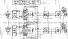
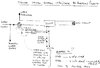
I think that perhaps a logic gate operated by transistors (H-gate type of circuit?) would achieve this performance. I am not an electonics expert, but I believe PN2222A transistors would be capable of this function.


However, I am not sure of the circuit details. Anyone out there sufficiently knowledgeable to offer advice ie a circuit diagram with suggestions of component values?
 
If its just purely on off, then two relays will do the job..
1587293846909.png
 
Is this like an aircon zoning valve where it has limit switches to turn off the current or can it be powered continuously?

Mike.
 
OK guys, this is the full story!
I aim to pump well water through a ground source heat pump (GSHP). When the GSHP is inactive, ie powered down I need to isolate the well water from it, but still keep the well water available for a domestic supply.
So, I intend to use a small motorised valve that is opened and closed by reversing the supply polarity. This can be done easily with a DPDT mechanical switch but I need it to be automatic . The valve needs to be open when the GSHP is operating and closed when GSHP is inactive. Using the 220vac on/off status to the GSHP to feed a 12vdc supply to the valve seems like a good option. The tricky bit that I cannot get my head round is configuring a logic gate to operate similar to a DPDT mechanical switch. I think a transistor/s can be configured to deliver a solution, but my electronics knowledge is very basic-hence the cry for HELP!

They can, but it's complicated, and it's MUCH easier to simply use a DPDT relay - simply replace the DPDT switch with the relay contacts.
 
I like simple - but I cannot see how your suggestion will work. The proposed system is attached. I need to change the polarity when the main power is switched OFF- this is my only problem. Take a look at the attached diagram.
 

Attachments

  • motorised valve control.jpg
    motorised valve control.jpg
    366.2 KB · Views: 175
How would you connect your DPDT switch? - bear in mind that the valve requires power to move in either direction, your circuit shows the 12V disappearing when the manual switch/thermostat is opened.

Easiest way would probably be to use the existing 12V power supply to feed just the relay coil (or even better use an AC mains powered relay avoiding the need for the 12V power supply). Then have the 12V power supply (or a second one if using a 12V relay) powered from before the switch (so permanently powered) and feeding the valve via the relay contacts.
 
OK guys, this is the full story!
I aim to pump well water through a ground source heat pump (GSHP). When the GSHP is inactive, ie powered down I need to isolate the well water from it, but still keep the well water available for a domestic supply.
So, I intend to use a small motorised valve that is opened and closed by reversing the supply polarity. This can be done easily with a DPDT mechanical switch but I need it to be automatic . The valve needs to be open when the GSHP is operating and closed when GSHP is inactive. Using the 220vac on/off status to the GSHP to feed a 12vdc supply to the valve seems like a good option. The tricky bit that I cannot get my head round is configuring a logic gate to operate similar to a DPDT mechanical switch. I think a transistor/s can be configured to deliver a solution, but my electronics knowledge is very basic-hence the cry for HELP!

You can use a relay but really were this my project I would consider using an L298 H Bridge module. They cost less than $4.50 USD on Amazon for the board ready to go. They will handle two motors at 2 amps each. Makes for easy polarity reversal and control. Keep in mind the modules vary by manufacturer.


Ron
 
You can do it with voltage division if you dont mind a bit of current pulling on the converse relay, when the reverse relay is activated, then as long as the GSHP is a full disconnection then the reverse relay will win the current, and itll go backwards.

Note you have to modify the ohms, it has to be more load than the GSHP or it wont work.

**broken link removed**

I had to redraw that 1000000 times... sorry for all the reuploads. i think i have it right now.

Its doing it with controlled shorting, You have to get every traces resistance perfect, and its probably got bugs still..... Its actually quite challenging but if you get the design right its 1c to make. =)

You can actually just connect straight to the motorized valve like this, but if you want to do it how this forum would like it, just do it with relays or transistors going to the h-bridge, I bet youll be able to draw it right almost first time, your circuit looks good.
 
Last edited:
Im pretty sure that circuit will work, its not hard... I havent tested it, its just a current divider, it divides between the relay and the pump, then when the pump is disconnected, its divided between the relay forwards and the relay backwards, and the backwards is 10khz resisted, and the forwards as I see it in the circuit winds up being 21khz, so the reverse relay gets 2/3 the power of the forwards, so it should go backwards.

If you want it to run "better" just add transistors to it. =) I think the OP can handle it tho, its not difficult is it, the problem proposed here...

I'm unsure if you're a troll or not?, as I can see no other reason for posting random collections of words that have no meaning?.
 
Im pretty sure that circuit will work, its not hard...
No...

Ohms Law: The vave is rated at 12V 2W; that means the current is 2/12 = 0.167A and its resistance is 12 / 0.167 = approx 72 Ohms.

The lowest resistor in your circuit is 1K; that will pass just 12mA at 12V and as a divider with the valve the voltage across the valve would be 12 / (1000 + 72), * 72 = 0.8V

Not 12V and not enough to have any effect at all.....

Ohms Law is one of the most fundamental principles of electricity and electronics. If you do not understand and use that, nothing you say will make sense or be realistic.
 
Hi guys. I think I have come up with a simple electro-mechanical solution. My perception of the problem was "How to get the valve motor to reverse when the GSHP is powered down?" That is to say, the valve control needs to be entirely automatic in response to GSHP on/off status.
Two x 5 pin non-latching relays are connected to the motor in a "back to back" configuration.
With zero supply to the relay coils, the 12vdc motor rotates in one direction. With 5vdc supplied to the relay coils, the 12vdc motor is reversed. This motor opens and closes the valve supplying the well water to the GSHP. As is usually the case, the motorised valve has internal limit switches that discontinue the supply at the end of the actuation in both directions so it does not draw any current after completing its stroke. So when the GSHP is switched off, the 5vdc supplying the relay coils (400mW each) is also switched off (a redundant phone charger is sufficient). The answer is provided by an Omron G5LE SPDT non-latching relay from RS @< £1.50 each delivered, inc. VAT. The 12vdc supply to the valve motor is from my rummage box, but could even be a small long-life dry battery. Not a transistor in sight-just the way I like it (I'm a Mechanical Engineer)
I have attached the circuit diagram for your amusement, entertainment and comment (good or bad!). Thanks for all the varied contributions.
PS to be clear, the mains voltage motor on the right of the diagram is the GSHP compressor and nothing to do with the water valve motor.
 

Attachments

  • THE FINAL SOLUTION.jpg
    THE FINAL SOLUTION.jpg
    1.1 MB · Views: 182
Last edited:
Well, if you're so smart you should have shown off your skill earlier. Congratulations on having solved the problem previously, I am very impressed, you are truly extraordinaire!
 
Well folks, I just received the relays from RS and built a Heath Robinson, hard-wired (on a piece of scrap plywood!) lash-up as a prototype and it worked fine. If I hide it in a box will probably use it as the finished product. Pic attached fo your amusement.
 

Attachments

  • Prototype valve control.jpg
    Prototype valve control.jpg
    740.4 KB · Views: 181
Well, if you're so smart you should have shown off your skill earlier. Congratulations on having solved the problem previously, I am very impressed, you are truly extraordinaire!
I did in post 2...
 
Problem? There was a problem? :)

Ron
 
Status
Not open for further replies.

Latest threads

New Articles From Microcontroller Tips

Back
Top