Continue to Site

Welcome to our site!

Electro Tech is an online community (with over 170,000 members) who enjoy talking about and building electronic circuits, projects and gadgets. To participate you need to register. Registration is free. Click here to register now.

  • Welcome to our site! Electro Tech is an online community (with over 170,000 members) who enjoy talking about and building electronic circuits, projects and gadgets. To participate you need to register. Registration is free. Click here to register now.

Motorcycle Rectifier tester, need design help

Status
Not open for further replies.

Lucky

New Member
Hi All, It looks like i've found a place where I can pick someones brain...

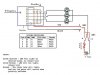
I am attempting to design a tester for my motorcycle's Regulator/Rectifier (really, just the diodes in the rectifier)
The tester needs to show that the diodes are not shorted, open and are passing current in the proper direction.

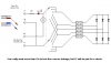
My knowlage of electronics is very limited, so excuse any incorrect symbols in my diagram. The LED's shown (not labeled) are dual color LED's I saw at Radio Shack, and had only 2 leads, so i'm guessing polarity determines what color lights up.

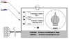
For referance, i'm trying to duplicate the test on Electrex's website: **broken link removed** Step "C"

My 2 questions are: 1) is my diagram correct so far, and 2) is there an IC chip commonly available that will take the place of the switches? In other words, what i'd like it to do is be "automatic", run test #'s 1,2,3,4 in sequence. (I have a 10baseT cable tester with a master & slave unit that does something similar, testing the wire pairs in a repeating sequence)

I'm trying to be detailed without talking over my own head :)
Thanks, --Lucky
 

Attachments

  • Copy_of_RRtester.JPG
    Copy_of_RRtester.JPG
    49.9 KB · Views: 1,191
Having a little trouble with your diagram. Since a diode only passes current in one direction, your red and black wires will only indicate when the polarity selected is in sync with the diode conduction path. If you have drawn the rectifier pack correctly, the tester will only work w/SW2 in one direction. Double check your diagram - especially the direction of the individual diodes. As to automation, you might consider a multi-gang rotary switch.
 
Reg/Rec wiring

Hi, thanks for the quick reply.
The rectifier portion of the R/R is directly from the Yamaha Manual. (cut & paste) so the diode setup is how it is in the piece. Other than x-raying the R/R there is no way to be sure that the drawing from Yamaha is correct, the R/R is permanantly sealed in epoxy. This R/R has been used in several different modle bikes and if the drawing were wrong, I have no doubt it would have been corrected in the manual long ago, simply because the tests would have allways come out backwards.

The standard method of testing the R/R is to use a DVOM set to diode (not Ohms) and test for voltage thru each white wire in both directions (by reversing the leads) so there are actually 12 tests in all.

results for 6 of the tests should be 1.5v or higher (red DVOM lead to red output wire, Black DVOM lead to each white wire in turn, = 3 tests, Black DVOM lead to black R/R (neg output), red DVOM lead to each white wire in turn. = 3 tests.

the other 6 test results should be about 0.50V (black DVOM lead to red output on R/R & red DVOM lead to each white wire in turn = 3 tests,
& red DVOM lead to black output wire on R/R, Black DVOM lead to each white wire in turn

I probably should have mentioned that the white wires are comming from the stator, and unused current is shunted to ground (this thing makes a lot of heat) the tester would plug into the 3 white wires, & the black & red wires. I just didn't show it on my drawing. the individual diodes in the Rectifier section are part of the component to be tested, not led's.

I didn't know how to correctly draw the 2 color led's, so i took my best guess. (it's actually green & blue, but whatever) like I said, the ones i saw in the store only had 2 leads, so i'm guessing at their construction.

long winded I know, but i'd rather be more detailed, rather than making you guess what i'm thinking.

As to a rotary switch, i'm shooting for making the tester idiot proof, I'd like to have someone using it just "look at all the pretty lights flashing" :wink: that's why i'd like to know if there is a simple ic chip available to do this, or at least a simple circut a neanderthal like me could understand.

Thanks! --Lucky
 
Ok, I think it is safe to assume the drawing is correct. I can't tell what connections are being made - where the diodes connect to each other (?) and it looks like all connect to the three white outputs. I doubt that all of this is connected together.

As to the two-wire LED - it is red/green (although it really does not matter at this point and you are correct that reversing the flow of current will change the LED color.

The circuit. When SW1 is in the "A" position (as shown), the + current flows to the cathode side of the lower diode bank. Unless a diode is shorted, the current stops here. A diode conducts in the other direction. To check the lower bank, the + current will probably have to enter the module from the white wire.

I think you are on the right track and I feel sure that there is a solution. The key to circuit design is the knowledge of what the wiring is inside (that center area that I mentioned earlier).

The reason they recommend an ohm meter is so that a difference can be detected between a conducting diode and a shorted diode. You can do the same thing with your tester because a shorted diode will conduct in both directions.

Just a thought...do these thing go bad often?
 
regulator/rectifier

The regulator/rectifier diode pairs (from ground to positive 12 volts) each connect to one white wire. The alternator has 3 output wires, which correspond to each of the white wires. So, the left most diode pair is attached to the top white wire, the middle pair is attached to the middle wire, and right most diode pair is attached to the bottom white wire.

Each LED (dual color) is attached to one white wire, and then all three LEDs are connected together and attached to one side of the DPDT switch. Originally, the red and black wires were connected without SW2, and attached to the opposite side of the DPDT switch.

The DPDT switch is used to reverse the polarity of the battery/resistor.

I would draw this up, but I am able to at the moment. I hope this makes sense and clarifies Lucky.

Lucky would like to see a digital solution mimicing the test outline he gave a reference to. It's a common test to verify the diodes in an auto or motorcycle rectifier using a diode tester.

As far as whether these burn up often, the unfortunate answer is yes. They are mounted over the rear exhaust manifold on a V-twin motorcycle, and they tend to burn out.

brian
 
Here is one solution. For the resistor, you will need to experiment a bit since we don't know how much voltage is lost in the diodes. You can start with 470 ohms and drop until the LEDs glow. When the single DPDT switch is in the position shown, it is testing the lower 3 diodes. When the switch is flipped, it is testing the upper bank. This will check for open diodes and burnt out circuitry (which I suspect is the major problem) but it will not detect a shorted diode (which is rare in my experiance). This is a low tech - partial solution but it is something you can build for less than $20.
 

Attachments

  • diode.jpg
    diode.jpg
    9.9 KB · Views: 956
changes made for clarity

If I understand diodes correctly, the will pass some current in both directions. The trick will be making the led's light up only when the proper voltages (1.5v or higher in the "wrong" direction, and roughly .50v +/- .10v in the "right" direction, sorry I don't know the proper term.

what components would I use to power the led's only at a given voltage, or a given range of voltage?

Testing thru both the Red & black wire is needed to insure that the complete circut is tested. Since the black (neg output) wire carries shunted current to ground, it is prone to failure. (the connectors commonly melt) It is generally accepted on our Forum that the connectors should be removed & soldered. corrosion in the connectors are a big cause of burnt stators & R/R

BTW, Brian has been helping me with this set-up as well, he is also a member of our M/C Forum

the automatic switching is now a secondary concern, but I don't want the idea to get lost.

Thanks, --Lucky
 

Attachments

  • RRtesterv1a.JPG
    RRtesterv1a.JPG
    57.7 KB · Views: 897
Please read the first sentence...

https://www.pbs.org/transistor/science/info/diodes.html

This is why your circuit will not work when you feed positive current to the red wire (the diode cathodes) - unless motorcycle diodes are different form all others.

To discriminate between discrete voltages, I would recommend a comparitor chip. This may be the solution to the detection of shorted diodes versus good ones but designing a circuit that critical will require more than the understanding of the diode. In addition the circuit will have to be designed specifically for your diode pack. It could be added to my pervious circuit.
 
I read it (and bookmarked it for further reading later) and that's how i've allways understood diodes to work too, in one direction. but for whatever the reason the testing procedures given in the fault Finding Chart on the Electrex site work. (see my first post, it's in .pdf format or i'd have cut & pasted a copy here)

i may have mispoke, when I said voltages (or not?). a diode tester mesures Voltage DROP across a diode, so perhaps i'm asking for the wrong kind of results?

so for now i'll accept the possability that the diodes used in these rectifiers may be "different" and will produce a voltage drop in both directions (and i've run the DVOM test on several, both good and bad, and the test is accurate) I just want to put the test in a led (hell even a wheat bulb, I don't care) format so that those in our group can plug this thing in & get a go/nogo result...
thanks for your patience, eagerly waiting to hear what you think,
--Lucky
 
Rectifier Tester

This is a three-phase rectifier pack, it uses normal power diodes.
Maybe there is some interference from the regulator circuit but this should be minimal below the bike's rated battery voltage.

I believe there is a mistake in your testing procedure chart - see modded below - when the rectifier diodes are reverse biassed there should be no LEDs lit.

As there are four states to test (2 positions * 2 switches) this could be automated with an oscillator (a 555?) and a flip-flop or two (counter circuit?), with some driver transistors (six in my idea).
The circuit would cause the bi-colour LEDs to go through a four-step sequence of green-blue-off-off which could be duplicated on a fourth LED.
All you would have to do is watch the four LEDs; if they all do the same thing then all is OK, any missing, extra or wrong colours indicate a fault.

You said you have minimal electronics experience so I don't know if this is too much for you or not ... :?: I could draw it up if it helps ? (2 ICs and 6 transistors).
 

Attachments

  • RRTesterV1b.gif
    RRTesterV1b.gif
    4.8 KB · Views: 858
Testing circuit

I'd like to see what you're thinking...

I've been working with Lucky on this a bit, and the problem I've been running into is the reversing of the polarity across the diodes. I can't quite figure a way of doing that.

That and keeping the chip count down to a reasonable level...

Brian
 
Tester Circuit

OK try this for a theory ...

The diagram has three links A, B and C, these connect to the matching points on the bit of diagram I 'stole' from lucky...

If the 555 timer runs at about 1Hz then the LEDs (all of them) should spend 2 seconds not lit then 1 second green, then 1 second blue and repeat. Any mixed colours (blue & green together) or missing LEDs means 'fault'.
The circuit has two LEDs to show what colour should be lit - thus making the whole thing that much easier to read - the strange connectios to the LEDs allows them to light only when the truth table says they should.

The 'D' type MUST be a positive-edge triggered type in order to satisfy the truth table (shown as 'D' in the table).

I have added a 38ohm resistor in the RED lead just to limit the current if there is a multiple diode short - one upper and one lower would short out supply if unchecked - maybe it could be better positioned in the 9v supply to the driver transistors but either would work.

:idea:
Maybe the 555 timer will give enough out to allow the removal of the driver transistors for output 'C' and use the 555 directly? so maybe only 4 transistors.

I figure the truth table for this (from lucky's diagram - corrected) to be
Code:
A B C D | Grn Blu
--------+--------
1 1 0 0 |  1   0    - NOR unique state (comparing 'C' and 'D')
0 0 1 1 |  0   1    - NAND unique state (comparing 'C' and 'D')
1 0 0 1 |  0   0    - green will light for a shorted diode (fault)
1 0 1 0 |  0   0    - blue will light for a shorted diode (fault)
I had an earier version posted before I realised if 'B is high when 'A' is low then all the diodes are forward biassed and so short out the 9v supply :oops: 
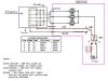
The NAND and NOR gates do some re-encoding to avoid this state.

Isn't blue and green a strange mix of colours ? Oh well, who cares :!:
 

Attachments

  • Four-state-Machine.gif
    Four-state-Machine.gif
    16.4 KB · Views: 843
I made some changes to the schematic to incorporate what you said, and added questions (I saved a copy without the notes :) )

sometimes I wish I could just talk to one of you guys and say "ok, if I put my finger here, and runt it along this witre to that component, it'll do what?" lol. I'll learn...I hope :)

--Lucky
 

Attachments

  • Copy_of_RRTesterV1b1.GIF
    Copy_of_RRTesterV1b1.GIF
    23.9 KB · Views: 793
ok, did some research & I think I have a handle on what a NOR & NAND do, and I get the basic idea behind the 555, but I need a little more info on the other things I have in red there, Thanks!, --Lucky
 
Bits for circuit

The circuit shows a red line for +9v and a blue line for 0v, these are just the 9v battery pos and neg terminals.

Components could be ...
NAND = 4011B or 4011BE
NOR = 4001B or 4001BE
'D' Type = 4013BE
NPN transistors = BC183 (upper ones in my diagram, right hand ones in yours)
PNP transistors = BC213 (yep!, lower ones!)

The transistors are happy switching upto 200mA and the LEDs should only need half that.
Have a look at **broken link removed** for more info on 'D' type.
 
************************************************************************

Hi Lucky,

Ive been thinking about your diode pack tester for a while now. I have
had motorbikes myself, and i know many people who have motorbikes.
Problems with the charging system can be a headache for many people.

Ive read through 'Dave's Yamaha Vision Page' which i think is excellent
very informative and very well written, and touches on many problems i
have had to deal with. It also mentions 'Lighting Coils' which i haven't
met before. I get the impression that they are a bit of a off-roader
item, intended to lighten the overall weight. I would like to find out
more about these 'Lighting Coils'.

Back to the diode pack tester, i think this is a fairly basic request,
and i think that a fairly basic circuit could be made to do this job.
I assume you would be making this unit yourself, and presumably you
have done this job of testing the diodes in the manner described in the
handbook, that is by checking each one individually in both directions
in order to see by means of a small electric lamp, that each one will
conduct one way, and will not conduct the other way.

I presume you have done this job and therefore realise it is really
simple, and you rightly assume that some sort of circuitry could be put
together to do this for you.

I have looked at your circuit, and yes the concept is ok. It is clear
that you have replaced the manual actions of touching wires on the
diodes each way round, with two switches which when operated alter the
connections to try the supply each way round, and again on the other
bank of three diodes.

This shows that you have a clear understanding of what you want the
circuit to do.

I prefer to use filament lamps to do these sort of tests because LEDs
will often light up quite adequately on fairly small currents, a
filament lamp of about 21 watts will require just under 2 amperes to
flow through the diode under test and i feel that is a better test.
I know headlamps can be much more than that, but the load would be
spread over them all normally. So i wouldn't use a headlamp on them
individually.

The LEDs would be more suited to checking for leakages, that is the
current that gets through 'the wrong way round', since these diodes
are connected to windings that can give much more than 12 volts out,
Dave's site puts some at around 50 volts no load, then maybe two or
even three 12 volt batteries would be a fairer test. This could test
the reverse current leakage at 24 or 36 volts.

You may ask: "Why check them at more than 12 volts when its a 12 volt
system?"

Well the reason is that the drive to the diodes is AC, which goes just
as far negative as it goes positive. When it goes positive and holds
the battery at 12 volts thats fine, but then it goes negative to minus
12 volts ... so the diode has twenty four volts across it, and its not
supposed to let any current leak back out of the battery.

If the engine were started with no battery connected, or a dry battery
the diode would have the un-loaded output voltage to contend with.
Which can be quite high, Dave's site puts it at about 50 volts on each
winding. I would expect those diodes to withstand about 100 volts in
the reverse direction to be safe.

Without making too much of it, i would guess that two or three 12 volt
batteries in series would show up any likely failures.

Making test equipment using chips and logic circuits can be difficult
and very frustrating for someone who is unfamiliar with such work.
I would suggest using a rotary switch instead.
When wiring up to a rotary switch, one can follow the wire with your
eyes, you can see which lug or connector on the rotary switch is
touching on each bit. You can compare it with your diagram, and see
that current should flow with each switch position to each lug or
connector.
Using a rotary switch one could follow each setting in turn by looking
at them and following where they go.

I don't know if you are still considering suggestions for this tester,
if you are you may like to look at this.

Regards, John :)
 

Attachments

  • Diode_Tester.jpg
    Diode_Tester.jpg
    28.7 KB · Views: 359
Circuit
 

Attachments

  • Diode_Tester_Circuit.jpg
    Diode_Tester_Circuit.jpg
    22.8 KB · Views: 363
As you can see in the diagram above, three positions on each wafer
of the rotary switch are duplicated and reversed, for each set of
diodes. In that drawing the six positions counting clockwise will
correspond to the six diodes counting one two three across the
upper row, and four five six across the lower row.
The position its drawn in is applying to the first diode, one.

If the forward check is being done the filament lamp should light.

If reverse volts are being applied the LED should not light.

In the original i had a switch to switch between these two, but i
got worried that someone might have two or three batteries doing
a leakage test ... and what if the switch got switched ... it would
blow the bulb probably. so i thought plug-in leads might be safer.

But if you're going to stick to 12 anyway, then you could fit a
switch instead of those plug-in leads.

I have tried to go for simplicity here, so that it can be easily
understood. Electrics is not everyones cup of tea.

Regards, John :)
 
Status
Not open for further replies.

Latest threads

New Articles From Microcontroller Tips

Back
Top