fouadalnoor
Member
Hello guys,
I am currently trying to run a motor off a programmed chip (PICAXE 08M) by using an N-Channel Enhancement MOSFET (2N7000). Without connecting the output of the chip to the MOSFET it works fine (the LED on my testbed is ON). After I connect the Output of the chip to the gate of the MOSFET the motor turns on as expected, but then after a few seconds it will just turn OFF. Another few seconds it turns ON.
I can't figure out why this happens. If I just connect it to the LED again it's ON without any problems (as expected)
Any idea's why this is happening? Is it maybe noise?
-------------------------------------------------
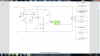
The Circuit is attached. Note that the BJT should be taken as an Enhancement N-Channel MOSFET as described above.
The data sheet for the motor is found:
**broken link removed**
The data sheet for the 08M PICAXE is attached.
I am currently trying to run a motor off a programmed chip (PICAXE 08M) by using an N-Channel Enhancement MOSFET (2N7000). Without connecting the output of the chip to the MOSFET it works fine (the LED on my testbed is ON). After I connect the Output of the chip to the gate of the MOSFET the motor turns on as expected, but then after a few seconds it will just turn OFF. Another few seconds it turns ON.
I can't figure out why this happens. If I just connect it to the LED again it's ON without any problems (as expected)
Any idea's why this is happening? Is it maybe noise?
-------------------------------------------------
The Circuit is attached. Note that the BJT should be taken as an Enhancement N-Channel MOSFET as described above.
The data sheet for the motor is found:
**broken link removed**
The data sheet for the 08M PICAXE is attached.
Attachments
Last edited:
