==================================
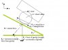
PLEASE REFER TO THE INCLUDED DIAGRAM
==================================
M = mass of the robot to be moved
r = wheel radius
g = acceleration of gravity
Fw = the force exerted by the edges of ALL the wheel and is the force being applied by the motors to move the robot up the slope
Ff = force of rolling friction
N = the normal force is the force exerted by the ground perpindicular to the ground which holds the robot up and stops it from falling through the ground. It is caused by the force of gravity and is one of two force components caused by the force of gravity (weight of the robot). These two terms will be used interchangeably.
Ff = this is the second component of the force of gravity and causes
the robot to want to roll down the slope
D = incline of the slope being travelled up. From simpl adding and subtracting 90 degree angles around the diagram, we find that the force triangle also has the angle D where labelled
To be able to roll the robot up the slope the force applied by the wheels must overcome the sum of the force of required to roll the wheels and the force causing the wheel to roll down the slope:: Fw > Fr + Ff
So, we must calculate these two forces, Fr and Ff:
We calculate force of gravity on the robot (the weight of the robot):
Fg = mg
Then we break this down into two force vectors to find the normal force, FR, and the normal force, N:
FR = Fg x sin(D)
N = Fg x cos(D)
So now we have FR, and we will use N to find the force of rolling friction, Ff:
Ff = uN
u is the coefficient of rolling friction. It is percentage of the normal force of the robot that must be applied to roll the robot along the surface. On flat ground, the normal force is equal to the weight of the robot (from the earlier equation N = Fg x cos(D) for D = 0º). So on flat ground (a 0º degree slope) u represents the percentage of the weight of the robot that must be applied to roll it. This value is always different depdending on the tires, mushiness of the tires, and the ground you are on. The values are pretty low so use some common sense in picking one.
0.3 is a VERY conservative value and means that 30% of the robot’s weight must be applied to roll it on flat ground.
0.1 (10% of the weight) is a good conservative value to go by.
The values can actually get VERY low, like 0.03 (3%) or 0.01(1%). For hard wheels on hard flat surfaces. So use whatever value feels good to you and is intuitively satisfying. Like trying “feeling” the forces required by lifting robots around your house and thinking about it.
Now that we have Fr and Ff we just add them up: Fw > Fr + Ff
Therefore, we need the force applied by the wheels, Fw, to be at least this much to get the robot to move. Remember, this is the force of ALL the wheels (or more importantly ALL the motors in the machine- it doesn’t matter how many wheels each motor drives. What matters is how many motors there are driving the wheels).
You can divide Fw by all the motors in the system in order to figure out the force required per motor. For all-terrain systems with many wheels (or designs where not all wheels may be on the ground at all times) you can use number of motors driving the minimum number of wheels that you expect to be on the ground at all times to account for the fact that some wheels (and their corresponding motors) will not be taking part in moving the robot in rought wobbly, tipsy terrain.
FM = forceper motor = Fw / [# of motors driving the robot]
OR
FM = forceper motor = Fw / [minimum # of motors driving the robot]
From here, if we know the wheel radius, r, we can figure out how much torque, T, each motor must apply to achieve the required force at the edge of the wheel.
T = FM x r
Remember that these calculations are only for moving a robot. The speed at which it moves is a different story. The more torque load that is placed on a motor, the more current the motor will draw and the slower it will spin. In order to get the robot to move up the slope at your desired speed, you must take a look at the motor’s torque-speed curves (and account for gear reduction if the graphs don’t do so ) and make sure that at the calculated torque, T, the motor will spin at the rotations-per-minute/second required to move your robot. The speed and torque required are dependent on wheel size.
-Bigger wheels, less RPM/RPS needed to move at a given speed, but more torque required to produce the same force at the edge of the wheel
-Smaller wheels, more RPM/RPS is needed to move the robot at a given speed, but less torque is required to produce the same force at the edge of wheel
The wheel speed and force will always balance out because although speed and force can change, power output of the motor always remains the same.
Here are the calculations to figure out speed from rotational speed (RPM or RPS) and wheel RADIUS (r):
Distance travelled per minute = π x RPM = π x RPS x 60
Distance travelled per second= π x RPM / 60 = π x RPS
Attachments
Last edited:
