Continue to Site

Welcome to our site!

Electro Tech is an online community (with over 170,000 members) who enjoy talking about and building electronic circuits, projects and gadgets. To participate you need to register. Registration is free. Click here to register now.

  • Welcome to our site! Electro Tech is an online community (with over 170,000 members) who enjoy talking about and building electronic circuits, projects and gadgets. To participate you need to register. Registration is free. Click here to register now.

Motor Drive Circuit

Status
Not open for further replies.

Kingpin094

New Member
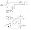
Does this circuit (see attachment) look like a good way to drive a 12V gear motor with stall current of roughly 700mA? (Vcc is 12V)

I built the circuit and it seams to work..... sorta. The motor spins quit nicely when the PWM is 100%.
There is little drop accross the H-bridge. When the PWM is set to below 100% ie. 90% the voltage
on the bridge drops from 11.5 to less then 6 and the transitors begin to get hot. The input logic
seams to function correctly and the bridge works if a'b = Vcc and ab' = GND (counterclockwise
rotation) and if a'b = GND and ab' = Vcc (clockwise rotation).

Anyone have any ideas on what could be wrong? Is this a good circuit or should I start over with
a different one?

Thanks ahead of time.
 

Attachments

  • motordrivecir4.JPG
    motordrivecir4.JPG
    38.7 KB · Views: 1,050
Your circuit is wrong. I have numbered the transistors Q1 for upper left, Q2 lower left, Q3 upper right.

When a' and b are High, transistor Q2 is on and Q3 and Q4 are going on/off alternatively as the PWM signal goes H/L.

When Q4 is on, the motor is acting as a generator and so current is flowing through Q4 and the lower left diode. Since there is not much resistance in this loop, a relatively high current will flow and so I suspect that Q4 will rise out of saturation and thus be dissipating significant energy.

You need to ensure that Q4 is off when Q3 is off. Likewise for Q1 & Q2.

Also, the 1N914 diodes are not suitable. I would use power diodes such as the 1N4004.

Len
 
The heating problem is due to the slow turn-off time of the transistors. When Q1 turns on, Q2 below it has not turned off so there is a short circuit across the power supply. You need to turn q2 off first, then turn Q1 on with a dead time of several microseconds.
 
why not use FET's ??? they are alot faster switching and dont need as much to drive tehm on. Also pretty much all FET's come with an anti-parallel diode this will reduce your component count.

Also you need interlocks. ie to stop a leg shootthrough.
Standard numbering for a single phase setup is

Q1 Q3
Q4 Q2

and for 3ph

Q1 Q3 Q5
Q4 Q6 Q2
 
I agree Styx. The main problem: with logic gates drivers the PNP transistors cannot close properly.
 

Attachments

  • h-bridge_307.gif
    h-bridge_307.gif
    9.5 KB · Views: 1,304
The reason I was using BJT's is that I had a bunch of them lying arround. I don't have
any FETS that can souce enough juice for a motor drive.

What if I put the logic gates on the 5 votl side and used the 23904's to drive the bridge. Do
you think that would help any? If i need to get some different parts I could but I was hoping
to make a working circuit with what I have on hand.
 
Of course You can use also BJT-s. Just try out the circuit, it work.
A logic gate can't give enough current to base driving, and the high-side PNP never closed properly.
 
The attached circuit will correct the problem with your logic circuit.

Len
 

Attachments

  • Motor_Drive.gif
    Motor_Drive.gif
    2.4 KB · Views: 958
Status
Not open for further replies.

New Articles From Microcontroller Tips

Back
Top