Electro Tech is an online community (with over 170,000 members) who enjoy talking about and building electronic circuits, projects and gadgets. To participate you need to register. Registration is free. Click here to register now.
Welcome to our site! Electro Tech is an online community (with over 170,000 members) who enjoy talking about and building electronic circuits, projects and gadgets. To participate you need to register. Registration is free. Click here to register now.
Atom you do know the AMC34063 is the same thing as MC34063A just AMC34063 they get for penny's and stick them in most all car chargers. There a bunch of part numbers for these chips.
Yeah i assumed that but those car chargers seem to break down quick so i wouldnt recommend it. All my friends have cars and they tell me about there chargers dont work and can you fix it and stuff heh.. i tell them go buy a new one.
I think you missed the point these are in them to MC34063A this is the same chip AMC34063. And I have never found a bad chip most are blown fuse or broke wire or a weak spring. I get all of them I can find just for that chip. and the inductor. Most free and some in a bag full of old chargers.
Be a good chip for Triode he can boost 3.5 volts up to 12 volts if he wants and run it till is dead. But I wouldn't no that to LiPo Cells
You can get batteries for free from old phones at the "drop off" ponts in most phone stores.
Use two 600mAHr cells in SERIES. This will give you at least 7v2
Or 2 x 2 = 4.8Whr
There's always plenty of ways to do something. For the batteries, I think AA would be a good size and shape, or AAA, the good news is I can probably fit a lot of them in the space provided, I got a look at the costume she's making and the strands are going to go in some butterfly wings, the support tubes that house the LEDs are 3/4" inside diameter, I can't put batteries at the ends, but if I load them up in the bases of the tubes I could probably put like 12 AA's in there.
I think I will try using some of the power conversion chips Be80be mentioned, I've wanted to learn more about those anyway even if it doesn't work out for this project.
I'm thinking I misread this datasheet the first time though
"
The ULN2801A-ULN2805Aeach contain eight darlington transistors with common emitters and integral suppression diodes for inductive loads. Each
darlington features a peak load current rating of
600mA (500mA continuous) and can withstand at
least50V in the offstate.Outputsmay be paralleled
for higher current capability"
Based on that doesn't it sound like I could just use a parallel set of 20 LED's on it? 30mA @ 3.4V * 20 in parallel = 600mA @ 3.4V. Am I wrong, or could I just parallel the outputs of one chip by twos to get 4 outputs that handle 1A each, and power a string off of each pair?
So then you also recommend a boost circuit? It does seem like for these applications these are the way to go, and Be80be and Atomsoft know their stuff, so I'll see what a MC34063 can do.
So using the site Atomsoft posted (**broken link removed**)
If I split the strings into two sets of 10 each, which it seems I could easily do, the output voltage would only be 35, I could use 6 of the 1.3 volt batteries that fit in the tube in series for 7.8V for that the calculator suggests these values:
Ct=321 pF
Ipk=405 mA
Rsc=0.741 Ohm
Lmin=135 uH
Co=29 uF
R=180 Ohm
R1=1k R2=27k (35V)
I'm not sure how using the closest real values will effect this though, converting to nearest real values it would be
While were on components, am I right in thinking that Ct is ceramic and Co should be electrolytic? And will a 1N4001 work for the diode shown at right?
So, what if I use one converter circuit to get a 35 volt output, use a ULN2803 after that (rated at 50V 500mA per gate), with each gate controlling a string of 10 LEDs in series, put the 7.8 volts from 6 AA size batteries through a 5V regulator to run the microcontroller, and connect the 8 control pins of the ULN2803 to 8 outputs on the microcontroller. I'm going to keep rewriting my plan till it's good.
the INDUCTOR must be able to handle the output current.. i still dont understand 2 sets of 10... is it like
Set 1:
ANODE ---|>|---o---|>|---o---|>|---o---|>|---o---|>|---o---|>|---o---|>|---o---|>|---o---|>|---o---|>|---o CATHODE
Set 2:
ANODE ---|>|---o---|>|---o---|>|---o---|>|---o---|>|---o---|>|---o---|>|---o---|>|---o---|>|---o---|>|---o CATHODE
? if so dont you simply add the dropout voltage ? What leds are you using most have a 1.5v dropout i think. which is minimum to turn on . 1.5v * 10 = 15v @ 20mA each... so 15v @ 40mA max
As for other values remember most passive components come as +/- 5% or something so you should be safe with closest value. If in doubt try to simulate it in proteus... thats what i do
Yes, the way you drew it is what I have in mind. It's just because if I put all 20 in series it would be 70V which the transistors I have can't handle. If I just use the minimum voltage wont the LEDs be really dim?
be80be Your solution is totally impractical. You have absolutely no idea how to connect LEDs in series/parallel. Sit back and let others give advice. You have obvioulsy never put LEDs in a circuit like this. I could not think of a worse reply.
Where is master Lol if there was one I have not seen it number one I went with there figures of 1.5 witch is not right I new that it would take a supply at 15 volts to light the leds right
I think some one need to give a Led 101 here if a led forward drop of a red led is about 1.85 volts now if you string them like I showed you will be dropping about 1.85 a led
Let's do the math here 8 leds x 1.85 = 14.85 volts will light all the leds
8 leds 198 Milliwatts x 10 = 80 leds 1980 Milliwatts = 134 Milliamps my way
You are doing 2 things here...
if its 1.85v each red led then there are 10 LEDs in a row. So its 18.5v needed. Since its series the current stays the same as 1 led. So 18.5v @ 20mA will light up 10 Red LEDs with a 1.85v drop.
If its in parallel then its 1.85v needed to power the 10 LEDs but with 10 x 20mA - 200mA
For 10 in Series its : 18.5v @ 20mA
For 10 in Parallel its: 1.85v @ 200mA
P = Watts
P = I * V
For Series : .02 x 18.5 = 0.37 Watts
For Parallel: .2 x 1.85v = 0.37 Watts
Thats funny tho... If your DVM says 14.85v and its 13.4mA then the resistance should be more like 1.1K Im sure resistance for a led is different for different suppliers
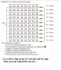
Solution 0: 8 x 10 array uses 80 LEDs exactly
+----|>|----|>|----|>|----|>|----|>|----|>|----|>|----|>|---/\/\/----+ R = 10 ohms
+----|>|----|>|----|>|----|>|----|>|----|>|----|>|----|>|---/\/\/----+ R = 10 ohms
+----|>|----|>|----|>|----|>|----|>|----|>|----|>|----|>|---/\/\/----+ R = 10 ohms
+----|>|----|>|----|>|----|>|----|>|----|>|----|>|----|>|---/\/\/----+ R = 10 ohms
+----|>|----|>|----|>|----|>|----|>|----|>|----|>|----|>|---/\/\/----+ R = 10 ohms
+----|>|----|>|----|>|----|>|----|>|----|>|----|>|----|>|---/\/\/----+ R = 10 ohms
+----|>|----|>|----|>|----|>|----|>|----|>|----|>|----|>|---/\/\/----+ R = 10 ohms
+----|>|----|>|----|>|----|>|----|>|----|>|----|>|----|>|---/\/\/----+ R = 10 ohms
+----|>|----|>|----|>|----|>|----|>|----|>|----|>|----|>|---/\/\/----+ R = 10 ohms
+----|>|----|>|----|>|----|>|----|>|----|>|----|>|----|>|---/\/\/----+ R = 10 ohms
The wizard says: In solution 0:
each 10 ohm resistor dissipates 4 mW
the wizard thinks ¼W resistors are fine for your application
together, all resistors dissipate 40 mW
together, the diodes dissipate 2960 mW
total power dissipated by the array is 3000 mW
the array draws current of 200 mA from the source.
This site uses cookies to help personalise content, tailor your experience and to keep you logged in if you register.
By continuing to use this site, you are consenting to our use of cookies.

")