Continue to Site

Welcome to our site!

Electro Tech is an online community (with over 170,000 members) who enjoy talking about and building electronic circuits, projects and gadgets. To participate you need to register. Registration is free. Click here to register now.

  • Welcome to our site! Electro Tech is an online community (with over 170,000 members) who enjoy talking about and building electronic circuits, projects and gadgets. To participate you need to register. Registration is free. Click here to register now.

MOSFET woes

Status
Not open for further replies.
I have recently started to dabble in building my own circuits. Its been fun and frustrating at the same time.

My project is relatively simple in its current stage. All I would like to do is to take a 30v 1a power source, convert it down to a low voltage to power the MOSFET gate and then have the full 30v be controlled by the MOSFET. I have attached a schematic of how I have everything wired (forgive me if its not properly done)

**broken link removed**

So now my problem... When I apply the 3.3v from the regulator to the MOSFET gate the source voltage is only 0.8v. if I increase the output voltage from the regulator I can increase the source voltage. If I go up to
10v from the regulator I get around 8v from the MOSFET.

I'm not to sure what is happening. The MOSFET gate threshold is only 2 - 4v it seems like 3.3v would be enough to open the gate. Maybe I am missing something. Here is a link to the MOSFET data sheet:

http://www.datasheetcatalog.org/datasheet/irf/irf510.pdf

If anyone could please help me with this issue I would be very grateful. I've been at this for two days and I am out of ideas.
 
There are a number of things that are not correct for the application that you are attempting to implement...

First, in regards to the N-Channel MOSFET, the voltage applied to the Gate must be in reference to the Source. Second, 3.3V applied across the Gate-Source junction may be enough to get the FET on, but you want to use this as a switch, so 5V wouldn't even be enough to get the FET fully enhanced. You want to apply 12V across the Gate-Source junction of the IRF510. Which brings us back to the first point. Let's say that the FET is ON and you have some type of load tied between the FET Source pin and Ground. What is the voltage going to be on the Source pin? With the FET fully enhanced and 1A flowing through the load (and by default, the FET), the Source pin would be sitting at around 29.5V. If you need 12V across the Gate-Source junction to get the N-Fet fully enhanced, then the voltage at the Gate pin (with respect to Ground) would have to be 42V.

In short, you are using the wrong type of MOSFET for the application. You want to get yourself a P-Channel MOSFET. Connect the Source pin of the PFET to the 30V source and the Drain pin of the PFET to the load. There are a numberr of different ways to control the PFET gate, which in turn will control the voltage to the load, but one way would be to tie a resistor across the Gate-Source pins of the PFET and then tie a resistor from the Gate pin to a switch and then tie the other end of the switch to ground. The resistor divider should be set up so that when the switch is ON (so that the resistor tied to it is shorted to ground) the voltage across the Gate-Source is -12V and the voltage across the resistor tied between the Gate and the switch is 18V (with respect to ground).
 
The N-channel Mosfet can be used to switch the negative wire of the load to ground. Then its source is grounded and its gate voltage can be +10V to +12V to fully turn it on.

The "2V to 4v gate threshold voltage" allows the Mosfet to conduct a minimum of only 250uA. The datasheet shows it fully turned on with a gate to source voltage of 10V.
 
I think im getting this...

Thank you both for your informative replies. I understand my dilemma a little better :) I do however have a few more questions as some of the imformation conflicts a little.
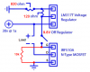
Using the same schematic in my earlier post I was able to get about 11v to the gate by increasing the 470 ohm resistor to 1200 ohms of resistance. The source voltage increased, but not nearly as high as I would like. I think it was around 8 - 10v. I was under the impression that the whole point of a MOSFET was to allow switching of a higher voltage by using a lower voltage.

I am putting the source to ground using my tester to check my voltages but my results are unimpressive. My ultimate question is using the parts I have what should the theoretical gate voltage need to be in order to pass 30v from the drain to the source? It really doesn't even have to be 30v I would be happy with 24v. I know there is a point at which the gate will burn out and I would have to cook parts; I've already managed to cook one some how.

Thanks again for your replies and information.
 
Make it like this.
The LM317 has an output of 9.8V which is fed to the gate through the switch to turn on the Mosfet.
The Mosfet is turned off by the 10k resistor.
The load is at the drain of the Mosfet so it gets the full 30V when the Mosfet turns on.
 

Attachments

  • Mosfet circuit.PNG
    Mosfet circuit.PNG
    109.3 KB · Views: 160
Thank you!

That worked perfectly. I will have to rethink my idea for the rest of the project due to my misconception of the way a MOSFET works, but this certainly puts me in the right direction.

It's satisfying knowing all the work and testing I have done finally resulted in something (wouldn't have been able to do it without a little help though :D).

Thanks again for your help.
 
Status
Not open for further replies.

New Articles From Microcontroller Tips

Back
Top