Continue to Site

Welcome to our site!

Electro Tech is an online community (with over 170,000 members) who enjoy talking about and building electronic circuits, projects and gadgets. To participate you need to register. Registration is free. Click here to register now.

  • Welcome to our site! Electro Tech is an online community (with over 170,000 members) who enjoy talking about and building electronic circuits, projects and gadgets. To participate you need to register. Registration is free. Click here to register now.

MOSFET pull down in linear region

Status
Not open for further replies.

Matt111111

New Member
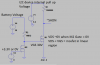
I have a current sense IC powered directly from a battery. I want the current sense IC to be in the shutdown state when the 3.3V power supply is disabled.


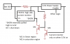
I have added a dual N channel MOSFET circuit (see attachments) to achieve a pull down on the shut down pin (active low and internally pulled high) when the

3.3V supply is not present. The circuit seems to work in LTspice but I am concerned about one of the MOSFETS operating in the linear region. (VDS < VGS - VT)


Is it safe to operate the MOSFET in this configuration or is there anything I'm missing that is considered bad design?
 

Attachments

  • 1.png
    1.png
    18.6 KB · Views: 250
  • 2.png
    2.png
    20.4 KB · Views: 242
It will work just fine. Just use logic level NMOS. In fact, the "linear" region is right where you want the MOSFET to be. Not sure what your concern is. When a MOSFET operates as a switch it's jumping between cutoff and "linear". M2 is no different in this regard. Could it be that you have mistook the "linear" region to be the same thing in a MOSFET as in a BJT?

It's really messed up and back-asswards terminology between BJTs and MOSFETs. Just never use the terms "linear" or "saturation" and always verify what someone really means when they do. "Saturation" is the technically correct term but means opposite things for BJTs and MOSFETs, while "linear" is a technically correct term for MOSFETs and only MOSFETs. The problem is, people use "linear region" to mean something different for BJTs when it's not actually the correct term and then they carry over the meaning when talking about MOSFETs when it already has another meaning for MOSFETs.

MOSFET:
https://i.stack.imgur.com/nnFhZ.png

NPN:
**broken link removed**

As you can see, everything is back-asswards with regards to the terms "linear region" and "saturation region".

Then you get garbage like this that uses steals terms from both NPN and MOSFETs and uses them at the same time:


All that said, is there a reason you need M2 and the pull-up resistor? I would just have M1 be driven directly by the 3.3V enable. The block diagram on page 7 of the datasheet indicates SHDN already has a current source acting as the pull-up so you don't need anything external.
 
Last edited:
Both schematics have 30 V on the gate of M1. Most MOSFETs have a 20 V limit.

The LT*C*4151 has a shutdown input threshold of 2 V. Why not connect the 3.3 V output directly to the shutdown pin and eliminate both transistors?

The difference between operating and shutdown is only about 1 mA. Is it worth it?

ak
 
Last edited:
Read what AnalogKid said.
If you do build this; M1 will brake with a VGS = 30V.
Two options.
1) Get the gate voltage from V1 6.3V.
2) Make a voltage divider to limit VGS to less than 20V.
upload_2018-1-17_13-27-28.png
 
Status
Not open for further replies.

Latest threads

New Articles From Microcontroller Tips

Back
Top