Continue to Site

Welcome to our site!

Electro Tech is an online community (with over 170,000 members) who enjoy talking about and building electronic circuits, projects and gadgets. To participate you need to register. Registration is free. Click here to register now.

  • Welcome to our site! Electro Tech is an online community (with over 170,000 members) who enjoy talking about and building electronic circuits, projects and gadgets. To participate you need to register. Registration is free. Click here to register now.

MOSFET not performing to datasheet spec (Vgs)

Status
Not open for further replies.

ACharnley

Member
Hi,

The FET is a very low Vgs turn-on with 27mOhm @ 2.5v. Apparently.

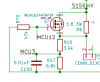
I have 5.5v connected to the drain, a capacitor over the source and a voltmeter over that.

I connect 0v to the gate. Voltmeter measures 0v.
I connect 3.3v to the gate. Voltmeter measures 2.6v.
I connect 5.5v to the gate. Voltmeter measures 4.8v.

So it looks like the Vgs is considerably higher than the datasheet spec. I've verified the component code and I'm in the process of validating with RS Components (UK) the fets were sourced directly. Any other ideas?

Oh, I've tried 5 of them so far!

The last one I pressed into the place thinking perhaps they are damaged by soldering heat.

https://www.tme.eu/hu/Document/d468925bfe2879f649e8ee0ff5de94a0/irlml6244pbf.pdf

Cheers!

Andrew
 

Attachments

  • Screenshot_2017-10-02_16-45-53.png
    Screenshot_2017-10-02_16-45-53.png
    90.9 KB · Views: 117
I do not understand. Like this? When you measure the Gate voltage, is the meter connected to "0 volts"?
upload_2017-10-2_10-48-1.png
 
The MOSFET is seeing Gate voltage from Gate to Source. Not Gate to ground. Go back and measure across the G to S pins. They you will see the part is working right.
 
Also check that you have drain and source connected properly and not backwards.
 
A drawing, schematic, sketch, or picture of your setup would be helpful, since Vgs is not necessarily equal to either the voltage gate-to-ground or source-to-ground.

You may not care about the voltage gate to source, but the mosfet does. If you load is connected to ground, then when the fet tries to turn on, the load/source junction will rise in voltage thereby decreasing the gate/source voltage and shutting the part off. I would assume (due to the lack of clarity of the connections in the OP) the voltages you are reading on the voltmeter is the fets happy medium between fully off and fully on due to the amount of gate-source voltage available.

Since the Fet acts as a switch, can you put the load on the drain side? This would keep the source pin grounded thereby (1) guaranteeing the gate voltage you apply is (2) the gate-source voltage seen by the fet and (3) by your voltage meter connected to ground.
 
Ah ok I think I've got it.

Source has to be connected to ground for the gate to open up, so the load has to be placed between +v and drain. This works (tested).

What I don't get is how that transfers to using the FET in a buck (see screenshot), i. e if I apply a DC +5.5V input, apply 3.3V to base, the voltage over the load will only reach the voltage figures posted previously.
 

Attachments

  • Screenshot_2017-10-02_12-39-25.png
    Screenshot_2017-10-02_12-39-25.png
    6.3 KB · Views: 114
A drawing, schematic, sketch, or picture of your setup would be helpful, since Vgs is not necessarily equal to either the voltage gate-to-ground or source-to-ground.

You may not care about the voltage gate to source, but the mosfet does. If you load is connected to ground, then when the fet tries to turn on, the load/source junction will rise in voltage thereby decreasing the gate/source voltage and shutting the part off. I would assume (due to the lack of clarity of the connections in the OP) the voltages you are reading on the voltmeter is the fets happy medium between fully off and fully on due to the amount of gate-source voltage available.

Since the Fet acts as a switch, can you put the load on the drain side? This would keep the source pin grounded thereby (1) guaranteeing the gate voltage you apply is (2) the gate-source voltage seen by the fet and (3) by your voltage meter connected to ground.

You've got it. :)

Now to understand how it'll work in a buck. When I apply a 5.5V PWM with a > 50% load the maximum voltage I can get is around 2.5V. I suppose this will open up when the load consumes power thereby allowing the FET gate to drain and the Rds to lower but that poses a difficulty in measuring the buck output under no/light load?
 
Source has to be connected to ground for the gate to open up, so the load has to be placed between +v and drain. This works (tested).

Yes and No. The voltage gate to source must meet what is in the datasheet. When the source and the meter are both connected to ground, then the measured gate voltage appears on the meter. When the source is not connected to ground but the meter is connected, then both the gate and source must be measured and subtracted (gate - source). If you placed the ground lead of the meter on the source and the red lead on the gate, then meter is showing you directly the gate-source voltage.
 
And in this one, the FET isn't bypassing R8 if J1 has a high resistance (i.e charged capacitor). Is this where it makes sense to use a P-Channel?
 

Attachments

  • Screenshot_2017-10-02_19-12-47.png
    Screenshot_2017-10-02_19-12-47.png
    7.2 KB · Views: 114
I connect 3.3v to the gate. Voltmeter measures 2.6v.
I connect 5.5v to the gate. Voltmeter measures 4.8v.
LTspice thinks the voltages should be 2.67V and 4.88V. That's pretty close!
FETvoltages.PNG
 
The Source will pull up to almost 5.5V when the MOSFET is turned on good.
When the MOSFET is off the voltage will drop down until D7 is on. (-0.7V) If the inductor is working.
For the MOSFET to be on the Gate must be above the Source by 2 volts. (more voltage is good)
So here I drive the gate to 7.5V to bring the Source up to the 5.5V supply. (10V would be better)
To turn off the gate needs to be very close to the Source at -0.7V. (0V is OK, but not any more)
upload_2017-10-2_13-6-57.png

A P MOSFET might be better for what you are doing.
 
As Ron noted a P-MOSFET is better for a positive output buck regulator (and is typically used for that purpose) since you don't need a separate drive voltage for the gate that's greater than the input voltage .

For that configuration, the P-MOSFET source is connected to the input voltage and the drain to the inductor.
That way you just ground the gate (Vgs = input voltage) to turn it on and connect the gate to the source (Vgs=0), to turn it off.
 
OK, so where possible I'll ground the source to allow for a full turn-on. For post #12 (reattached) the current limiting resistor can move to the bottom (which is where I originally had it) then I can bypass it with the N-FET. The only consideration here is I have to do two ADC conversions to calculate the voltage level across the pins (which are super-capacitors).

I'm confused regarding the buck, if an off-the-shelf buck IC can pass 40V using an internal N-FET how is it being done? VGS rating is rarely above 20V.
 

Attachments

  • Screenshot_2017-10-02_19-12-47.png
    Screenshot_2017-10-02_19-12-47.png
    7.2 KB · Views: 97
So like this but a second detection required from pin 2 to gnd to work out the voltage across pin 1 & 2.

Which is why I'm wondering if a P-Channel is the better option here?

But if the P-Channel has 5.15v on it's input and a gate v of 3.3v to turn it off, technically the Vgs delta is enough to pass some current and would probably be enough to destroy it.
 

Attachments

  • Screenshot_2017-10-02_23-54-29.png
    Screenshot_2017-10-02_23-54-29.png
    4.9 KB · Views: 99
Last edited:
Lets start over.
You have 5 to 5.5 volt supply?
What is you load? motor?
It looks like a 1.8 ohm 3 watt resistor will run the load but you want to send more power under control of a computer?
Does it matter if the load is connected to ground or +5V?
You need to measure the voltage on the load?
Is your computer running on 5V or 3.3V? (output pin voltage 0V and 5V?)
If you are using "PWM" output, what frequency?
What micro computer?
 
Too many questions, my schematic has gone to **** :) and I'm trying to sort it out.

Let's start with this one as I believe it encompasses all the issues.

What it is is a large super-capacitor with a resistor to rate limit the charge. Unfortunately the resistor offers a slight reduction in efficiency and fet's are cheap enough, so the idea is to bypass the resistor once the voltage over the super-capacitor reaches a pre-determined amount. The charge voltage is 5.15v. The MPU offers TTL 3.3v. FET turn on is from 1.5V. A partial turn on is unacceptable (heat could destroy it).

The MPU will calculate the voltages and turn the FET on. Options so far;

Resistor is at the top, N-channel at the top. I now believe this won't work as the Vgs delta won't reach the sensible "turn-on" level once the capacitor voltage is near 5.15v. The VGS will be 1.8v so in destruction territory if current is drawn.

Resistor at the bottom, N-channel at the bottom. The VGS sinks to ground so the FET will be controlled correctly, however in order to calculate the voltage of the capacitor two readings must be took between 5.15v line and gnd and the resistor to gnd. One minus the other gives the capacitor voltage level.

1. am I talking bollocks
2. is there a better way using P-channel

My understanding with P-channel is that it is by and large the same in that the gate must be pulled to the source voltage for a complete turn off. Driving it to 3.3v won't be enough. Sure I could use a 100k resistor from source to pull it high but voltages outside TTL could cause complications on the MPU.
 

Attachments

  • Screenshot_2017-10-02_19-12-47.png
    Screenshot_2017-10-02_19-12-47.png
    7.2 KB · Views: 103
  • Screenshot_2017-10-02_23-54-29.png
    Screenshot_2017-10-02_23-54-29.png
    4.9 KB · Views: 101
P-FET, S=5.15V, D to J1
R70 pulls the G to S to turn off the MOSFET. Could be 10k.
Added a transistor like MPS2222a to turn on the MOSFET. Gate-Source voltage 0/5V.
If MCU12 is high, MPS2222a is on and pulls GATE low. (G to S voltage is about 5V)
upload_2017-10-2_17-55-1.png

edited-------
MPS2222a and two resistors could be a N-MOSFET (no resistors) Low current/ low voltage is fine.
 
Last edited:
Status
Not open for further replies.

Latest threads

New Articles From Microcontroller Tips

Back
Top