Continue to Site

Welcome to our site!

Electro Tech is an online community (with over 170,000 members) who enjoy talking about and building electronic circuits, projects and gadgets. To participate you need to register. Registration is free. Click here to register now.

  • Welcome to our site! Electro Tech is an online community (with over 170,000 members) who enjoy talking about and building electronic circuits, projects and gadgets. To participate you need to register. Registration is free. Click here to register now.

MOSFET half-bridge

Status
Not open for further replies.
Hi there,

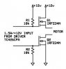
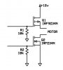
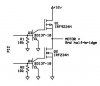
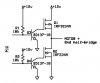
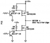
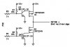
I have posted about this problem before, but the MOSFET transistors continues to break down or the circuit doesn't work. I want to build a MOSFET H-bridge to drive (PWM-control) DC motors up to 24V. I started by doing this half-bridge to se if it works.

When I turn on the driver, which outputs 12V/1.5A nothing happens. I have built the circuit exactly as the circuit tells and I have handled the MOSFETs with ESD protection.

Isn't it right that you can use two N-channel MOSFETs in stead of both a P and N-channel for this kind of circuitry?

Any ideas?
 

Attachments

  • Half-bridge.JPG
    Half-bridge.JPG
    13 KB · Views: 3,151
You can use two NMOS for the high end, but then you need a higher gate voltage to switch the MOSFET since the source (and hence the gate trigger voltage) is now being referenced to something higher than ground. You seem to have taken care of this with the pull-up resistor, but does the driver you are using function properly to work this way?

High-end MOSFET:
High Impedence Gate (effectively a high due to pull-up)- ON
0V Gate- OFF

Low-End MOSFET:
High Impedence Gate (effectively a high due to pull-down)- OFF
+V Gate- ON

"Opposite" signals switch your MOSFETs differently due to the way the pull-up/down resistors are. A signal that switches on MOSFET will turn the other off. You also need to use a high impedence state to make the pull resistors effective. DOes your driver do all this?

You also want to stick reverse biased diodes in parallel with each MOSFET to handle the flyback.
 
Last edited:
dknguyen said:
...but does the driver you are using function properly to work this way?

What do you mean by that?

What is the difference between a N-channel Power MOSFET and a NMOS?
 
Last edited:
N-channel FET and NMOS are the same thing. Power just means it's built to handle high currents.

I updated my previous message while you responded.
 
Your top Mosfet needs a gate voltage of 22V to fully turn on. Driver ICs for Mosfet H-bridges make the extra high voltage.

Or you can use a P-channel Mosfet at the top and it turns on by grounding its gate.
 
So the circuit can look like this?

What voltage on the gate is then required to turn the MOSFET off? A least 10V? So I will need a MOSFET driver to control the circuit with a PIC?
 

Attachments

  • Half-bridge2.JPG
    Half-bridge2.JPG
    9.3 KB · Views: 726
Be careful though because the maximum gate-source voltage is 20V for all MOSFETs.
 
In stead of using IC drivers could the driver be built with effect transistors like the BD137-10, and then just send in a 5V PIC signal to ground? the MOSFETs?

Should there be some resistors some places?
I know I'm missing the reversed biased diodes.
 

Attachments

  • Half-bridge3.JPG
    Half-bridge3.JPG
    16 KB · Views: 995
  • Half-bridge4.JPG
    Half-bridge4.JPG
    16.8 KB · Views: 553
Last edited:
1) Your P-channel Mosfet was upside down.
2) Your Mosfets didn't have a transistor collector resistor to turn them off.
3) Your transistors didn't have series base resistors to limit the current from the pic so it doesn't smoke.

This circuit will operate slowly because the 10k collector resistors charge and discharge the high gate capacitance slowly. Mosfet driver ICs are much quicker and most have built-in voltage boosting circuits so that all Mosfets can be N-channel.
 

Attachments

  • Half-bridge3.PNG
    Half-bridge3.PNG
    25.6 KB · Views: 5,865
Why are you even using a half bridge for a motor? I don't see the point - it's only going to drive the motor in one direction. You might as well just get rid of the upper FET and drive the motor with a low side FET making sure you have a free wheel diode across the motor. If you want bi-directional control, then use a full bridge.
 
I am going to do a full H-bridge as described in the beginning. The reversed biased diodes are as well in the circuitry. The half bridge were for test only.

I have modified the circuit. Can this do it (open for almost 12V through the bridge with the signal from a PIC), or are the pull-up/down resistors wrong?

And how to calculate the total amount of current to the motor with the resistor values to base/gate?
 

Attachments

  • Half-bridge5.JPG
    Half-bridge5.JPG
    18.6 KB · Views: 640
Your circuit won't work. Look at my last one.
1) Your upper P-channel Mosfet doesn't have a resistor beween its gate and its source (the transistor's collector resistor) to turn it off.
2) Your lower N-channel Mosfet doesn't have a resistor between its gate and the +12V supply (the transistor's collector resistor) to turn it on.
3) The max base voltage of the transistors is +0.7V. The output voltage of the PIC goes up to nearly +5V and provides plenty of base current in each transistor. Then the pullup resistors are not needed.
 
Electronics4you said:
Yes, but isn't the power consumption dependent of the DC current gain in the transistor?

No, why would that have any effect?. The voltage on the base of the transistor will be roughly 0.7V, the gain makes no significant difference to that.

For rough calculation purposes, you can assume zero volts on the base (as 0.7V isn't far from zero), so you have the full drive voltage across the resistor. The error from ignoring the 0.7V is on the correct side, and the figure returned will be slightly higher than in reality.
 
You're probably already aware of it, but I'll mention it just in case...Make sure you switch those fets properly. if you turn both fets on on either half of the H, you'll have a short circuit. (Shoot through)
A nice thing about those Half bridge driver IC's is that they provide some dead time in between firing the top and bottom fet.

I just built an h bridge using 2 IR21844 driver's. I tried testing 1/2 of the circuit like you did and I couldnt get the top fet to fire. I had to build the whole thing to get it to work right.

Also, you may want to look into a current monitor/ cutout circuit. I had a mosfet failure or something and it resulted in a pretty good amount of smoke, (and melting my breadboard a bit)
**broken link removed**

I'm gonna be drawing up a schematic of the circuit I used in the next few days, I'll try to post it if I remember.
 
Will the transistors in the circuit make the input low, when a PIC signal is applied on the base of the transistor?

The upper MOSFET:
This need a low signal (0V) to fully open, so when the FET gets a low signal the voltage applied to the gate is +12V, right? When the signal goes high the 12V will flow through the collector-emitter to GND, so the MOSFET will get the low signal on gate to open.

Couldn't the lower FET to drive the NMOS be turned around, so it's normally providing the MOSFET gate with a low signal when no PIC signal is applied? The pull-up resistor must then be turned into a pull-down resistor. Then both transistors need a PIC signal to turn on, which is easier to operate with.

I didn't knew that problem could occur when only testing half of the bridge. That shouldn't have something to say...
 

Attachments

  • Half-bridge6.JPG
    Half-bridge6.JPG
    16.7 KB · Views: 1,622
The circuit has big BD137 power transistors, not FETs, driving the gates of the Mosfets. You don't need big power transistors. Little BC547 transistors will be fine.

You can remove one transistor and connect the gates of the Mosfets together and have a single signal make the output go high and low. But both Mosfets will turn on at the same time for a moment and short the supply and probably blowup the Mosfets.
It is best to have the upper Mosfet controlled separately from the lower Mosfet so your driver circuit can allow some dead-time between one Mosfet turning off and the other Mosfet turning on. Mosfet driver ICs have dead-time built in.
 
Status
Not open for further replies.

Latest threads

New Articles From Microcontroller Tips

Back
Top