Continue to Site

Welcome to our site!

Electro Tech is an online community (with over 170,000 members) who enjoy talking about and building electronic circuits, projects and gadgets. To participate you need to register. Registration is free. Click here to register now.

  • Welcome to our site! Electro Tech is an online community (with over 170,000 members) who enjoy talking about and building electronic circuits, projects and gadgets. To participate you need to register. Registration is free. Click here to register now.

MOSFET H-bridge switching spikes

Status
Not open for further replies.
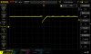
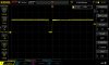
The first picture is the spike at pin 2 of the 555 IC4 when the input at C4 (output optocoupler) is low. The second is at the same location, with input at C4 high. The spikes have the same frequency as the h-bridge. Mind the x-axis time: to make the second spike isible (it is a lot longer than the previous one) I had to extend the time base to 50uSec per division.
 

Attachments

  • DS1Z_QuickPrint40.jpg
    DS1Z_QuickPrint40.jpg
    70.1 KB · Views: 96
  • DS1Z_QuickPrint41.jpg
    DS1Z_QuickPrint41.jpg
    69.6 KB · Views: 100
Interesting.

However, when the scope ground clip is connected to the circuit ground then there should be no issue: the power supply is not connected to ground, hence floating, and will follow the scope ground. No?
No. The power supply almost certainly is isolated for DC due to its power transformer, but its output is not isolated for AC signals due to capacitance between windings in its transformer and other places...
 
No. The power supply almost certainly is isolated for DC due to its power transformer, but its output is not isolated for AC signals due to capacitance between windings in its transformer and other places...
The signals annexed in my previous post are rather stable.

And spikes occur at the h-bridge frequency, not really affected by mains noise. So the issue remains: how to eliminate these spikes?
 
No. The power supply almost certainly is isolated for DC due to its power transformer, but its output is not isolated for AC signals due to capacitance between windings in its transformer and other places...
After several hours testing I must agree with part of MikeMI's comments: stray capacitances do affect hte circuit, and putting prototypes on breadboard is not ideal at all. Isolating the pulse length detection circuit from the rest proves that the bridge circuit interferes; when placing a 1.000uF cap across its rails did that part get solved: no interference with the pulse detction circuit.
Adding a few more large caps on the rails right next to the optocoupler, increasing R14 (series resistor on optocoupler input), and adding a 100nF cap across the optocoupler input pins 1 & 2 got the circuit working as it should.

Further optimisations will have to be tested, but at least: thank you for those having responded here so far!
 
Status
Not open for further replies.

Latest threads

New Articles From Microcontroller Tips

Back
Top