Continue to Site

Welcome to our site!

Electro Tech is an online community (with over 170,000 members) who enjoy talking about and building electronic circuits, projects and gadgets. To participate you need to register. Registration is free. Click here to register now.

  • Welcome to our site! Electro Tech is an online community (with over 170,000 members) who enjoy talking about and building electronic circuits, projects and gadgets. To participate you need to register. Registration is free. Click here to register now.

mosfet gate drive circuit

Status
Not open for further replies.

Chippie

Member
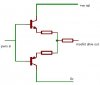
I've built a pwm controller with a mosfet as the power device...It would appear that my gate drive voltage is insufficient to saturate the mosfet...this is leading to becoming a little too warm for comfort...

Most pwm circuits I've come across drive the gate direct, presumably with no issue!

Supply rail voltage for the circuit is currently 12v with a view to increasing to 15v if need be...

Is there a discrete gate drive circuit I could use to aid driving the mosfet or do I have to go the commercial route? (dont really want to do that if I can help)

Offers of advice appreciated...
 
Is the mosfet high-side or low side? Are you sure it's the conduction that is making it warm, or a slow switching rate?

Schematic?
 
Gate drive of 12 V should be enough to saturate any MOSFET. have you scoped the drain voltage yet? Is the drain voltage doing something silly, when it's supoosed to be down at deck?

Some circuits, if you're driving the gate with something weak like a 4011, it ain't a strong enough drive. CMOS output drive is fine for switching lamps and relays, but not for most PWM. What can happens when you try turn on the fet (especially with high voltage on the drain), is as the drain voltage flies down, a current pulse gets coupled into the gate (via the drain / gate capacitance), the opposite of what you are trying to do and then the fet turns itself off for a while as the capacitance charges. Result warm fet.

One way you can bolster up the drive is to connect a wad of 74HC244's in parallel as a gate driver. Or use a TC4427 like blueroom suggests (easiest)
 
Last edited:
Ok I threw together a bit of a sketch of a gate driver.....

comments?

As for the schematic, its just a 555 timer conf'g'd as a pwm driving an IRF540...the load is a motor that's drawing around 4-5 amps...Frequency is around 23-24kHz...

I've just measured the gate volts and my scope is telling me that its around 14-15v pk-pk...
 

Attachments

  • gate driver.JPG
    gate driver.JPG
    9.8 KB · Views: 19,320
Last edited:
Remove the resistors. They are not needed.

If you're driving a high-side switch, you're going to need a boostrap diode and cap to give you the right voltage.
 
Hi Chippie,
You can connect the emitters of the transistors together and eliminate the two emitter resistors.
 
Thanks guys...

What about suitable transistors? small signal devices?
 
What would it be oscillating with? The inductance of the traces?
 
What would it be oscillating with? The inductance of the traces?

Series resistor in gate is a ritual. Included religiously. Differnt engineers express themselves with their favourite value. In a corporate setting, the value is dictated by the company and the engineer doesn't influence it much. You can tell a few things about someone or orgainsiation when they choice the particalur value.
 
The current rating of the driver transistors is determined by the total gate capacitance of the Mosfets and their switching speed because it takes a fairly high current to charge and discharge a capacitor quickly.
 
Status
Not open for further replies.

Latest threads

New Articles From Microcontroller Tips

Back
Top