The tiny DMP3010 Mosfet is perfect for your requirement, even if it has minimum or maximum spec's.
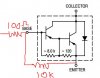
Guess what? The curves on datasheets are for "typical" devices that you cannot buy. The text in a datasheet shows the minimum to maximum range of specs. The saturation graph for a TIP125 shows 1.26V at an output of 3A and an input of 12mA but the text says a maximum saturation voltage of 2V.
1) Where does 12mA with a pull down from 5V to 2.0V (the maximum Vbe sat is about 3V) come from?
2) Will you accept an output saturation voltage of 2V or will you buy and test many TIP125 Mosfets and hope to fine a better one?