Continue to Site

Welcome to our site!

Electro Tech is an online community (with over 170,000 members) who enjoy talking about and building electronic circuits, projects and gadgets. To participate you need to register. Registration is free. Click here to register now.

  • Welcome to our site! Electro Tech is an online community (with over 170,000 members) who enjoy talking about and building electronic circuits, projects and gadgets. To participate you need to register. Registration is free. Click here to register now.

MOSFET Biasing with 5V

Status
Not open for further replies.

Suraj143

Active Member
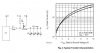
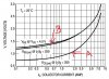
I want to drive the IRF9530 P Channel FET with 5V logic levels.My load is 3.2A. The problem is datasheet shows at 4.5V gate voltage, the drain current will be around 2.8A. Is there any simple modification to be done within the given hardware to supply required current?

I cannot use another driving transistor to drive the FET. Also I cannot find logic level MOSFETs in my area.

Minor changes will be proffered.
 

Attachments

  • Mosfet Volt.JPG
    Mosfet Volt.JPG
    69.6 KB · Views: 175
It also shows (Fig 1) that at 4.5V gate voltage and 3.2A current it will have a DS voltage of about 14V. Ouch, it can't work as you have it.

Mike.
 
Hi, Thanks.

I just load test by turning LEDs one by one in a row.What I noticed was when I have more LEDs on, the LEDs are getting dim.For the first few LEDS no problem.

I don't know what to do.
 
Measure that your 5V supply voltage is not dropping under the load, and look around for a different mosfet that is logic level. IRFP9530 is an old 100V with 300mOhm Rdson, which is way too large. Look for some more modern 30V parts.
 
Measure that your 5V supply voltage is not dropping under the load, and look around for a different mosfet that is logic level. IRFP9530 is an old 100V with 300mOhm Rdson, which is way too large. Look for some more modern 30V parts.
Agree, there are different P channel MOSFETs that will conduct more at 4.5V, such as the FQP27P06. Datasheet shows about 3A at 4V, and at 4.5Vgs over 10A current draw...
You just have to shop around for a MOSFET that draws more current at 4.5V logic levels.
MOSFETs like the NDP6020P are actually "logic level" P channel, that may be easier to find. RDSon is 0.05 ohms at -4.5Vgs, and even though they are rated for maximum 20V, they should be fine for a 5V circuit.
Good luck
 
The graphs on a datasheet are for a "typical" device but many have minimum or maximum spec's. The IRF9530 Mosfet is designed to use a 10V Vgs to fully turn on. Its maximum threshold voltage is 4V when it barely turns on with a current of only 250uA.

Which 5V logic family is driving your Mosfet? An old TTL 7400 IC has a minimum output high of only 2.4V, not 5V.

Can't you order a logic level P-channel Mosfet from a modern parts distributor?
 
A gate drive transformer will give you any gate voltage sensibly required.
 
Nope.
Oops I thought for some reason this was a switcher.
 
Can you re-write the code that drives the PIC pin that drives the gate?

Can you add any parts between the PIC pin and the gate?
 
Can you change it for a darlington transistor such as a TIP127 or TIP147? I'm not even sure if that would work either - anyone any experience in this situation?

Mike.
 
Can you re-write the code that drives the PIC pin that drives the gate?

Can you add any parts between the PIC pin and the gate?
Hi
*I can re write the code.

*I have two resistors, one is gate resistor and the other one is pullup resistor.So I have 4 pads in my PCB to do modifications .Anyway like to hear your idea.
 
Last edited:
Can you change it for a darlington transistor such as a TIP127 or TIP147? I'm not even sure if that would work either - anyone any experience in this situation?

Mike.
Hi thanks.That idea came to my mind first but forgot because of MOSFET recommendations.I guess that darlingtons have 2V saturation voltage drop over high currents.Today I will check by adding a pair & see.Not sure I need Heatsink on that device as well.
 
Hi Mike,

The TIP145 is a good choice.it will drop below 1V @ 3A current.Better than I thought.

Only problem don't know whether it can survive without a heatsink.

I will check it today.
 
Last edited:
Hi,I'm about to try a TIP125. But I'm bit of confused the graph showing in the datasheet regarding saturation voltage.There are 3 curves in the graph & which one is representing the saturation voltage?

VBE@ VCE = 2V
VBE(SAT) @IC/IB = 250
VCE(SAT) @IC/IB = 250
 

Attachments

  • TIP125.JPG
    TIP125.JPG
    80.3 KB · Views: 150
It's the lower "A" curve, the Vce one.

Note that if you use two separate transistors with the first one working as an emitter follower and a resistor from the emitter of that to the base of the second (plus a B-E resistor), the saturation voltage of the second transistor can be much lower.

A darlington is self-restricting to some extent as the first transistor feed is also from the collector, so it cannot truly saturate the second transistor.
Very useful info.Thanks
 
Can you change it for a darlington transistor such as a TIP127 or TIP147? I'm not even sure if that would work either - anyone any experience in this situation?

Mike.

Hi Mike & Others

I tested with TIP125 (TO-220 Package), & the performance were really better than the MOSFET.Also It won't heat at all.The saturation drop even low than I think. Really satisfied with the results.Also it cost cheaper than FETs.

Thanks
 
Status
Not open for further replies.

Latest threads

New Articles From Microcontroller Tips

Back
Top