Hello,
Please advise on how to model our Mains Input Filter in LTspice for our LED power supply.
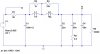
In our Non_switch_mode, offline LED current regulator, we have the Mains Input Filter as in the attached diagram “_Mains Input Filter”
We have done the AC sweep of it in LTspice by modelling the LED current regulator as a 10k impedance. (as in the attached LTspice schematic called “_Mains Input Filter _LTspice” We chose a high impedance because Current sources are high impedance.
Our LED current regulator works by kind of switching in different banks of LEDs as the mains rises and falls in the mains cycle.
So do you think it is reasonable to model the LED current regulator’s input impedance as a 10k resistor, as we have done in the schematic of the filter attached?
Please advise on how to model our Mains Input Filter in LTspice for our LED power supply.
In our Non_switch_mode, offline LED current regulator, we have the Mains Input Filter as in the attached diagram “_Mains Input Filter”
We have done the AC sweep of it in LTspice by modelling the LED current regulator as a 10k impedance. (as in the attached LTspice schematic called “_Mains Input Filter _LTspice” We chose a high impedance because Current sources are high impedance.
Our LED current regulator works by kind of switching in different banks of LEDs as the mains rises and falls in the mains cycle.
So do you think it is reasonable to model the LED current regulator’s input impedance as a 10k resistor, as we have done in the schematic of the filter attached?