Continue to Site

Welcome to our site!

Electro Tech is an online community (with over 170,000 members) who enjoy talking about and building electronic circuits, projects and gadgets. To participate you need to register. Registration is free. Click here to register now.

  • Welcome to our site! Electro Tech is an online community (with over 170,000 members) who enjoy talking about and building electronic circuits, projects and gadgets. To participate you need to register. Registration is free. Click here to register now.

MOC3032 Pull Down Resistor

Status
Not open for further replies.

ibwev

Member
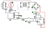
1) Assuming 5 volt supply with a desired current of 10 mA at Pin 1 of the MOC3032 (see diagram), should Rin be 500 ohms? R=V/I
=5/0.01
=500Ω
moc3032Resistor.png

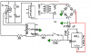
2) If I follow the datasheet of the MOC3032 and use a 1K ohm resistor at Pin 4 and open the switch to Pin 1, the Emitter of the triac remains high. If I change the 1K ohm resistor to a 590 ohm resistor then the Emitter of the triac will go low when the switch is opened. How do I accurately calculate the desired resistor size on pin 4 of the MOC3032? Note- I am using 24 VAC instead of the 115 VAC of the datasheet.

MOC3032PullDown.png
 
hi,
The forward voltage drop of the MOC emitter diode is 1.25V and the d/s says at 30mA.

So 5Vsupply - 1.25V =3.75V, I would use a 220R series resistor giving 17mA. [the d/s says 15mA is required]

On the 2nd circuit there are missing items so its not easy trying to see what you are trying to do.

example: missing triac Gate resistor, LM317 missing Adj to 0V etc...
 
hi,
Looking at the d/s for 240V and 115V AC operation, the pin6 resistor should be 36R

and the pin 4 resistor should be ~3.3K

Whats the RED ring resistor doing.???

E
 

Attachments

  • Moc schematic.png
    Moc schematic.png
    10.9 KB · Views: 304
Whats the RED ring resistor doing.???

Thanks you so much for the help. I think the "RED ring resistor" is serving as a pull down resistor (not sure I used that term correctly for alternating current). It is noted on the MOC3032 datasheet to be 1 kΩ (see below); however, the contactor will not open after the switch has been cycled if the "RED ring resistor" is 1KΩ. It will open and cycle with the switch if the "RED ring resistor" is 590 Ω.

moc3032Resistor.png


HOLD EVERYTHING. I believe I drew the schematic incorrectly. The "RED ring resistor" should be the gate resistor that E has calculated to be 3.3K. I will try that later today. Thanks again for the help.
 
Last edited:
hi
Relook at the image in post #5, you have a resistor in one of the 'anodes' not the gate/trigger, thats what I was querying.

I will look a the circuit , see why the contactor is not working correctly.

EDIT:

You have the Contactor/Triac connected incorrectly, I will post a corrected circuit.

Look at this circuit,
 

Attachments

  • Moc schematic.png
    Moc schematic.png
    10.8 KB · Views: 266
Last edited:
You have the Contactor/Triac connected incorrectly,

It's amazing what happens when I correctly assemble the circuit. The circuit is now working correctly. I really appreciate your time in helping me.

May I ask 2 more questions on your circuit from frame 7?

1) What risk do I run if I do not snub the triac with the RC Filter? The circuit appears to be working great without it.

2) Please help me with the 220Ω resistor on the anode pin of the MOC3032. I follow the voltage drop from Frame 2 above. However, if I am interpreting the datasheet correctly, it suggest using 10 mA for the series resistor to the anode pin (see attachment). Should the resistor on the anode pin be:
Resistor= (Voltage Drop)/Current
=(5-1.25)/0.01
=375Ω

datasheet moc led 2.png
 
It's amazing what happens when I correctly assemble the circuit. The circuit is now working correctly. I really appreciate your time in helping me.

May I ask 2 more questions on your circuit from frame 7?

1) What risk do I run if I do not snub the triac with the RC Filter? The circuit appears to be working great without it.

2) Please help me with the 220Ω resistor on the anode pin of the MOC3032. I follow the voltage drop from Frame 2 above. However, if I am interpreting the datasheet correctly, it suggest using 10 mA for the series resistor to the anode pin (see attachment). Should the resistor on the anode pin be:
Resistor= (Voltage Drop)/Current
=(5-1.25)/0.01
=375Ω

hi,
Thats good to hear.

The contactor is an inductive load so its possible that it could produce a high back EMF spike which could damage the triac or keep it switched ON.
Ideally with zero crossing detection switching of the 24Vac sine wave the triac should only be switched ON/OFF at 'close' to zero crossing of the sine wave.

For the low cost of the snubber resistor and capacitor I would fit them, this will reduce the chance of triac failure and also reduce any radiated electrical noise from the unit.

The MOC will work at 10mA OK, I would use a 330R which is the nearest preferred value.
The emitter is rated at a maximum current of 30mA, so 12mA will be OK.

E.
 
Status
Not open for further replies.

Latest threads

New Articles From Microcontroller Tips

Back
Top