Electro Tech is an online community (with over 170,000 members) who enjoy talking about and building electronic circuits, projects and gadgets. To participate you need to register. Registration is free. Click here to register now.
Welcome to our site! Electro Tech is an online community (with over 170,000 members) who enjoy talking about and building electronic circuits, projects and gadgets. To participate you need to register. Registration is free. Click here to register now.
Hi, does anyone know where to obtain the MiSim DE 2.1 Pic simulator by Feersum? I believe it was made freeware before being abandoned. As a newcomer to PICs I find MPLAB somewhat overwhelming.
Thanks, I found an old printout of a web page amongst my general bric-a-brac, while having a clearout, and found a program for using a small pic to drive a stepper motor with a ULN2803.
I thought it would be an interesting small project to begin learning about PICs.
I worked in Avionics all my life before retirement, and have no fears about electronics, but have slight knowledge of coding.
I thought I could port the program to a 12F509, and managed to get MPLAB 8.92 to compile the program as a 12F509, with some warnings.(which I do not understand)
I want to breadboard it (I have a Pickit3) but before that, I had thought to simulate the program using LEDs to monitor the motor drive outputs from the PIC, and have tried the demo of Real Pic Simulator, but although it has the 12F509 in it when I tried to run it I got an error message "Error out of code". An email to Digital Electo Soft evinced no reply, and as I don't know if it is a limitation of the demo version or something else, I am reluctant to spend any dosh yet.
I cannot understand the MPLAB simulator (especially the MPLABX version, I find MPLAB X very difficult to understand).
I have all the Oshonsoft compilers and simulators, but here is no 12C/F50x pic support.
I had hoped the Misim DE, being older might support them, but it seems unobtainable.
The Proteus simulator does support them, but is very expensive for the hobbyist.
Is it very difficult to port to a supported 8 pin PIC, say a 12F629? though they seem much more complicated.
here is the code from the (no longer available) website.
I also don't understand what
DELAY1 EQU 0C
DELAY2 EQU 0D
INDEX EQU 0E
mean, are they registers? or variables?
Code:
;    control a small stepper motor with a 12C509


;    There are two controls, run/stop and direction
;    The motor steps when the run button is depressed
;    If the direction button is pressed
;    the direction is reversed

;
;    Peter Lynch, 13 May 1998
;    pic@beowulf.demon.co.uk    (THIS SITE NO LONGER EXISTS newpicuser)

;    (this code is NOT certified Year 2000 compliant)

        LIST P=12C509        ; (deleted by newpicuser)

        include "\picde\12c509.inc"    ; (changed to #include <p12c508.inc> newpicuser)

OPMASK    EQU    B'11000000'
BMASK    EQU    B'00101000'    ; all bits output (except GP3 and GP5)
                ; GP3 controls run/stop
                ; GP5 controls direction

RUN_BTN    EQU    3
DIR_BTN    EQU    5

DELAY1    EQU    0C
DELAY2    EQU    0D

INDEX    EQU    0E        ; step index

    ORG 0

; start of main code

    MOVWF    OSCCAL
    MOVLW    OPMASK
    OPTION

    MOVLW    BMASK
    TRIS    GPIO

; now go into a loop, output the next bit pattern on
; GP0 - GP4 (GP3 is input only)

    CLRF    INDEX

NEXT

; check for run/stop button

    BTFSS    GPIO, RUN_BTN
    GOTO    NEXT

    BTFSS    GPIO, DIR_BTN
    GOTO    CWISE

    INCF    INDEX, W
    GOTO    NEW_IDX
CWISE

    DECF    INDEX, W
NEW_IDX
    ANDLW    .7
    MOVFW    INDEX

; here W contains the index (either incremented or decremented, depending
; on the direction switch) into the array for the new stepper actuations

    CALL    STEP        ; convert the index into a bit pattern
    MOVWF    GPIO
    CALL DELAY

    GOTO NEXT

; routine to get step index

STEP
    ADDWF    PCL, F
    RETLW    B'00000001'
    RETLW    B'00000101'
    RETLW    B'00000100'
    RETLW    B'00000110'
    RETLW    B'00000010'
    RETLW    B'00010010'
    RETLW    B'00010000'
    RETLW    B'00010001'

; routine to delay between steps

DELAY

    MOVLW    .10        ; 10 milliseconds per step
    MOVWF    DELAY1

DEL_0
    MOVLW    .250        ; 1 millisecond delay
    MOVWF    DELAY2

DEL_1

    NOP
    DECFSZ    DELAY2, F
    GOTO    DEL_1

    DECFSZ    DELAY1, F
    GOTO    DEL_0

    RETURN    ; (changed by MPLAB to RETLW 0 newpicuser)

    END
I will have to reinstall MPLAB 8.92 as it now longer runs since MPLAB-X updated itself to 5.10
Sorry for the long post, any help/comments will be appreciated.
Delay1 and 2 are simply a "count" to loop for to create a specific delay time in software. This would be based on the chip frequency. Since I don't see any frequency specification, I would assume the PIC is running at the default 4Mhz.
Index is a pointer into the "Step:" routine, to get a specific bit pattern for output.. It's like a program counter offset.
Hi,
Yes, just found that when I built your code, though the 12C chip is the one time programmable chip, you need to change the LIST and Include lines to 12F, which will build ok and then allow you to your your Pickit programmer.
You also need to Configure, Select Device and change the 12C to 12F
If you View, File Registers , you will see what those variable are.
Quiet a few of us in the forum started with Assembly code and one member , Nigel, has written a good tutorial you might find interesting, he is still around to help.
Afraid I have only used the most basic functions of mplab sim, perhaps other can help, though as you will see on the web etc a lot of folk use Proteus for simulations , though as will all of them there are limitations and bugs.
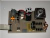
Personally still prefer to build and test my own hardware, for motors I made up a board with a couple of different types of motrs .stepper, servo, all just a few pound from a local hobby shop or online.
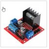
Just looked back about 8-9 years ago to find the motor board and assembly code I used, driven by the L298 motor chip which you can buy as a complete driver module for just a few pounds on the usual uk sites
Though using a larger chip, the 18F, it does contain some extra routines you might find of use in the future.
Index is added to the program counter in the "Step:" routine, to basically create a jump offset to the PCL. Index is a value that is incremented or decremented based on previous value. The returned value from the "Step" routine give the different pin outputs to step the motor.
The 12F509 is an older chip. Look into the 12F675, it is the same pinouts and is more common/easier to find. The Oshonsoft compiler will handle it just fine. You can find 12F675 real cheap on places like Ebay. The 12F683 is one step higher than the 675, and again, cheap to find. Both of those series have more features as well.
I'd strongly recommend not starting with the 8 pin PIC series as they cannot be used with in-circuit debugging.
You have a Pickit 3 which I believe does support in-circuit debug on devices that have that facility.
I find that invaluable - being able to step through a program running on "live" hardware makes things infinitely easier than working blind when trying to find a bug.
It also allows you to see what is happening with the CPU registers step-by-step and helps understand how the CPU is executing your program.
(There was at one time a special PIC12 IDC device, a 14 pin MCU with eight pins matching the standard PIC12 layout and extras to support simultaneous debug connections - but I cannot find any reference to those now, it looks like they are no longer made..)
(There was at one time a special PIC12 IDC device, a 14 pin MCU with eight pins matching the standard PIC12 layout and extras to support simultaneous debug connections - but I cannot find any reference to those now, it looks like they are no longer made..)
Yes, typically you see "b" lower case, but it depends on the assembler build settings, you have various options from the menus, like Case Sensitivity and Radix
OK, so I've managed to compile this code, but it doesn't run properly in MPLAB X simulator.
(Very steep learning curve.)
I am able to toggle the run/stop GPIO 3 and direction GPIO 5, but GPIO 0 only ever goes high and stays high.
I'm not sure what is happening with the ADDWF PCL, F as it doesn't seem to produce the output pattern to drive the ULN2803.
I've also run the program in the Oshonsoft simulator (great software by the way) with the stepper motor option and it only clicks to one pole then stops.
Can anyone suggest what to try? Where have I gone wrong?
I would like to persevere with the 12F509 as the newer devices seem more complicated just yet.
OK I've properly read the reply from Sagor1 about the STEP routine, but still don't understand why my program only outputs 1 step. I've added the config lines ( __CONFIG _MCLRE_ON & _CP_OFF & _WDT_OFF & _IntRC_OSC ) to the listing and recompiled it, to get the hex file.
Hm.... I think _MCLRE should be OFF. Having it on means you are doing a CPU reset/clear every time you press it.
GP3 has to be configured as input, not a reset.
Thanks, I've reconfigured and recompiled, but still the only activity I can see on the GPIO pins is the setting or resetting of the run/stop(GPIO3) and dir (GPIO5) pins.
GPIO 0, 1, 2, and 4 don't move.
Code:
;    control a small stepper motor with a 12F509


;    There are two controls, run/stop and direction
;    The motor steps when the run button is depressed
;    If the direction button is pressed
;    the direction is reversed

;

        #include <p12f509.inc>

    __CONFIG   _MCLRE_OFF & _CP_OFF & _WDT_OFF & _IntRC_OSC


OPMASK    EQU    B'11000000'
BMASK    EQU    B'00101000'    ; all bits output (except GP3 and GP5)
                ; GP3 controls run/stop
                ; GP5 controls direction

RUN_BTN    EQU    3
DIR_BTN    EQU    5

DELAY1    EQU    0C
DELAY2    EQU    0D

INDEX    EQU    0E        ; step index


    ORG     0x3FF             ; processor reset vector


    ORG 0

; start of main code

    MOVWF    OSCCAL
    MOVLW    OPMASK
    OPTION

    MOVLW    BMASK
    TRIS    GPIO

; now go into a loop, output the next bit pattern on
; GP0 - GP4 (GP3 is input only)

    CLRF    INDEX

NEXT

; check for run/stop button

    BTFSS    GPIO, RUN_BTN
    GOTO    STEP

    BTFSS    GPIO, DIR_BTN
    GOTO    CWISE

    INCF    INDEX, W
    GOTO    NEW_IDX
CWISE

    DECF    INDEX, W
NEW_IDX
    ANDLW    .7
    MOVFW    INDEX

; here W contains the index (either incremented or decremented, depending
; on the direction switch) into the array for the new stepper actuations

    CALL    STEP        ; convert the index into a bit pattern
    MOVWF    GPIO
    CALL DELAY

    GOTO NEXT

; routine to get step index

STEP
    ADDWF    PCL, F
    RETLW    B'00000001'
    RETLW    B'00000101'
    RETLW    B'00000100'
    RETLW    B'00000110'
    RETLW    B'00000010'
    RETLW    B'00010010'
    RETLW    B'00010000'
    RETLW    B'00010001'

; routine to delay between steps

DELAY

    MOVLW    .10        ; 10 milliseconds per step
    MOVWF    DELAY1

DEL_0
    MOVLW    .250        ; 1 millisecond delay
    MOVWF    DELAY2

DEL_1

    NOP
    DECFSZ    DELAY2, F
    GOTO    DEL_1

    DECFSZ    DELAY1, F
    GOTO    DEL_0

    RETLW 0

    END
Make sure you have a pull-up resistor on the two input pins. 10k ohms is usually good enough.
Depending on which compiler you use (and the chip you use), the _IntRC_OSC option may have secondary options like _IntRC_OSC_NoCLKOut or _IntRC_OSC_CLKOut (like on the 12F675). Make sure you have "NoCLKOut" if there is such an option.
EDIT: Ok, I checked the 12F509 in Oshonsoft, and there is no secondary option for the IntRC_OSC...
This site uses cookies to help personalise content, tailor your experience and to keep you logged in if you register.
By continuing to use this site, you are consenting to our use of cookies.