Continue to Site

Welcome to our site!

Electro Tech is an online community (with over 170,000 members) who enjoy talking about and building electronic circuits, projects and gadgets. To participate you need to register. Registration is free. Click here to register now.

  • Welcome to our site! Electro Tech is an online community (with over 170,000 members) who enjoy talking about and building electronic circuits, projects and gadgets. To participate you need to register. Registration is free. Click here to register now.

Miles per gallon gauge

Status
Not open for further replies.

valve-n-head

New Member
I m trying to make a gauge to directly display the miles per gallon for my vehicle. A signal from an optical encoder driven off the speedometer cable will yield a pulsed output proportional to vehicle speed in miles per hour. A flow meter inserted in the fuel line will generate a pulsed output in gallons pre hour. I need to know how to continuously divide the MPH signal by the GPH signal and display the quotient in MPG. Both signals can vary continuously. :?:

Any help will be appreciated.
 
In order to do this, you have 3 variables you must account for.
1. Miles driven
2. Fuel consumed
3. Time of operation
Assuming your sensors are calibrated as you stated, simply divide the total miles driven by total fuel consumed, adjusted for the total elapsed time since start of measurments. This would give you a running average that would become more accurate as time progresses. This will require something to provide data processing power and memory storage for the 3 variables.
Dialtone
 
what kind of car is it? and where exactly on the fuel line are you tapping into?

I know that on my '95 Chevy, it is constantly pumping fuel. Once it get's to the fuel rail, only a small portion of fuel is used. The rest is sent back to the tank. I'm not positive if this is true for older carborated cars or not. (I'm pretty sure it is though.)
 
Thanks for the reply guys. If anyone knows a better way to do what I want to do, please let me know, but I will need a schematic.
 
what kind of car is it going to be used on? maybe if the computer is good enough (OBD 2) there would be a way read how much fuel is coming out of each injector
 
The way this is done on modern cars is pretty simple. You tap the vehicle speed sensor for the distance, and the injector output for the fuel.

You can read 1 injector driver signal, with the duty cycle for that injector you can compute the amount of fuel being used, pretty easily.

With sequential injection you wont have perfect accuracy using only a single injector signal, but unless this is for scientific use, it'll be within 1%.
 
Fuel Monitor

I have an ancient (commercial :cry: ) MPG meter that uses a sensor in the speedo cable and a simple turbine sensor in the fuel line (carburettor).
To calibrate it you drive along at 30mph and press a button on the display, it does some math and stores this factor. All readings are then in MPG regardless of speed, the display would update about once a second.

An option on the installation allowed a sensor onto a HT line instead of butchering the speedo cable but then it would only work in one gear ratio - change gear and the readings would be garbage.
 
DirtyLude said:
The way this is done on modern cars is pretty simple. You tap the vehicle speed sensor for the distance, and the injector output for the fuel.

You can read 1 injector driver signal, with the duty cycle for that injector you can compute the amount of fuel being used, pretty easily.

With sequential injection you wont have perfect accuracy using only a single injector signal, but unless this is for scientific use, it'll be within 1%.

I've had a new Fiat Punto for about 18 months now, and it gives a dashboard display of MPG, along with how many miles you can do on what's left in the tank, and various other bits and bobs. Presumably it uses the fuel injection electronics to provide a reading of the fuel usage? - I can only presume it uses the fuel gauge to estimate how much fuel is left in the tank?.

However, since I took delivery I've been logging all my fuel purchases and milage readings - and although I haven't bothered working it all out yet (one day I'll bung it in a spreadsheet!), on a tank to tank basis I'm getting about 45 miles per gallon. The MPG reading on the dash usually hovers around 56 MPG though!. Obviously I don't rely on the reading for how many miles you have left :lol: but in any case, when it's getting low it lights a really annoying yellow LED, so I go and fill up when it comes on.
 
My 1999 GMC Suburban appears to have throtle body injection since there is no sign of a fuel rail or individual injectors and I do not know if any of the fuel is returned to the tank, probably is.

I recently found an unusuar frequency divider on www.wenzel.com that divided one frequency by superimposing one frequency on another. How do you superimpose one frequency on another one? The same circuit is also found on various other sites

Sounds like "machine" has essentially what I am looking for, I just don't know where to find anything like it, ancient or otherwise.

The only formal electronics training I have comes from my Air Force days and that was all related to the onboard equipment. Also it was in the late 50's and was all vacuum tube stuff. Thus I am really groping in the dark when it comes to solid state electronics. Please help!

Robert
 
1999 with TBI? thats not possible, it's fuel injected. the fuel rail is hidden under the plenum. That's definitly got the OBD 2 computer, maybe there is a way to monitor it by using the computer.

or maybe you could try using 2 flow sensors, one on the inlet line and one on the return, then just subtract the 2 to get the fuel used. there should also be a way to 'hack' the signal that goes to the odometer to get your distance traveled.

I thought it would be cool to have a mpg display while I'm driving, but it would be a little depressing due to the gas prices.
Instead I just calculate it whenever I fill up. I just fill the tank until it stops, then reset my trip odometer. Then I drive it, when I get gas again I fill it until it stops again. Which gives me the total gallons used. Then I divide the trip odometer reading by the gallons used. There's a little discrepency in it, because you can always squeeze a little more in. but it's good enough for me (and a lot eaiser than trying to hack the fuel system.
 
True, jrz126, I have been recording my milage and gas at fillup for several years bur I am planning to make some other experimental changes and I want to see the results as I drive.

As for taking info from the ECU for trip reading, not possible since these readings are all generated mechanically, no digital dash instruments on this buggy.

Recon I better get a set of manuals for the truck so I can determine just what-is-what on it

At any rate I will not make any changes until I can breadbnoard a circuit and verify the results first. But I have no idea just what kind of components are needed to do what I want to do. A circuit anyone?
 
To meet environmental regulations, just about every newer production vehicle since OBD2 (1996) uses sequential injection.

Very new cars (in the past few years) have started to use returnless fuel lines, but most use a pressure regulator to return fuel to the tank and maintain pressure at a constant level. The pressure regulator also maintains the pressure differential between the fuel rail and the intake plenum, so that 1 ms on time for the injector will flow the same amount of fuel at any intake pressure.

If you're thinking about an entirely passive solution, you can pretty much forget about it. It would be real simple with a microcontroller. Read the on time of the injector and average it over the number of kilometres traveled, taken from the speed sensor.
 
Hi valve-n-head,

Curious that this should crop up,
many years ago i made a 'mile-age indicator' for my old Mk2 Jag.

I looked at that frequency thing,
i dont think that will be of any help to you.
https://www.wenzel.com/documents/freqdiffdivide.htm

The arrangement i used on that old Jag was really quite simple,
although i didn't set the mileage very accurately,
cos i was not really concerned too much with the mileage,
i was more concerned with improving the mileage, and it did that
very well indeed.

Dialtone makes a good point about needing the right set of input
information, although the way i see it you only need two sets of
inputted information,
namely: distance and fuel.

In the arrangement i made i had an extra wire added in to my fuel
pump, and i fitted a light sensitive transistor arrangement into
my speedo-meter housing. The light sensor was set close to the
spinning part driven by the speedo cable, this i had sprayed
matt black and i had put white marks on it with a tippex marker.
(thats a white-out paint for typing errors in a tiny bottle with
a little brush in the lid like a fingernail varnish bottle)

The pulse from the pump i used as my fuel monitor.
The pulses from the speedo i used as my distance monitor.

The indicator was, and still is, a couple of seven segment displays.
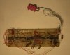
Although the unit has not been on the vehicle for many years, i
still have it knocking about somewhere ...
It was thrown together on a small 'bread-board kit' one of those
where you poke the component wires into a matrix-work of inter
connected holes.

Initially i thought that having it count up to the MPG, then doing
it again and again would be good enough for me to look at, and i
would just take notice of the final count each time.
Well that was a waste of time ... i needed it to stay at the count
number while i was driving! It was no good counting up continually.

So i modified the circuit a bit. The chips then included a buffer,
and the count from the speedo was fed through to the buffer opon
receipt of the fuel pump pulse. The trailing side of the fuel pump
pulse re-set the counter.

So that was much more use-able and see-able, the pump operated at
about two times a second at first, then when the auto choke dropped
out, went down dramatically to about four second intervals at
about its best tickover.

The pair of seven segment displays showed the count, as last put
in the buffer, and updated at each pump operation.

I couldn't be bothered to sort it out properly, and i had a common
resistor in the common line of the displays, instead of a resistor
in each leg as it should be. This meant that the 'one' was bright,
and the 'eight' was dim, but i did not care, i used it like that
for years.

I will try to set out the principle as clearly as i can, in case
it is still not clear. The unit does no calculations. The unit
counts the white marks on the speedo internal spinning disc which
is its reference to the car wheels. The count is forwarded to the
display each time the fuel pump operates. The fuel pump trailing
side pulse zeroes the counter.

So, on tick-over, standing at traffic lights, the fuel pump would
operate many times, and each time would forward zero to the display.

In overdrive, at a decent speed, i think about forty to fifty miles
per hour gave me the highest readings, thats the number of pulses
from the speedo, forwarded to the display at each operation of the
fuel pump.

I never got around to adjusting the number of white marks inside
the speedo, which could have been made to correspond to MPG,
cos i was more interested in getting it as high as i could.
Based on the mile-ometer and the gallons that went in, i reckoned
at about thirty five to forty miles to the gallon. Not bad for an
old 3.8 Mk2 Jag.

I will see if i can find the old board, and post a few photos.
It was pretty basic and simple.
If i find it, then it will have the chips, so i could post their
numbers too if you want. There weren't many components involved
as i recall, but i often don't remember things quite right, so
i will have a look when i find it.

Regards, John :)
 
Well i found it.
Pretty much where i thought it would be.
And covered in dust.

By the look of it, i had been trying to do something else
with it after i took it off the old Jag, but i don't recall what.

Theres a micro switch wired in, and a light sensor in the
bottom right corner, i may have to have a good look to see
what's what ...

Anyway, its basically intact, the two seven segment displays
are still there, larger one the right way up, smaller one on its
side, thats just cos they were the ones i had knocking about,
they're the two black lumps in the middle, one you can easily see
the red shape of the seven segment outline, the one on its side
is the same sort of item, but a bit smaller, and the legs are
differently arranged, thats why its on its side ...
it was put together in a hurry ...

left to right ...

7490
7475
7447
display
display
7447
7475
7490

If you want, i could pick it over and note the component values
and draw it out.

I may even fire it up and see if it still works.

just to re-cap,
it displays a number which is refreshed each pump action.
I dont recall if the leading zero is suppressed,
probably not.

John :)
 

Attachments

  • counter_102.jpg
    counter_102.jpg
    24.1 KB · Views: 720
:) hey john1, not sure if your trick will work on my GMC but it is a start. Thanks for the offer of a drawing, i will take you up on that. sorry for the delay, things get a little hectic here in the autum.

valve-n-head
 
valve-n-head said:
:) hey john1, not sure if your trick will work on my GMC but it is a start.
No, it wont work. It's like he missed everything that was said in the previous posts.

That would be fine if your GMC was carbed, but guarenteed it's not. The amount of fuel pumped by the fuel pump has no relation to how much fuel your engine uses.
 
I agree: on an old Jag it’s OK because it had a carburettor that means no return fuel line. And second, the old type of fuel pumps was membrane type where you actually had a fixed amount (almost) of fuel for each stroke. That could work pretty good I think.

For EFI engines you have to measure the fuel in both directions and calculate the difference, which then is the consumed amount. The other input can be from a sensor on a driveshaft if you don’t want to tap in on the electronics (tacho, cruise or ABS).


Ante :roll:
 
being an electronics newbie i have bneen reading a lot about some of the things mentioned in the posts. some of this causes more confusion due to my ignorance of the capabilities of things like PIC's and BS2's.

could someone tell me the specific difference between these two devices?

thanks for all the help!
 
well a pic is a microcontroller which is a very cool device which can be programmed by you to do just about anything from turning on an LED to controlling a robot .
a BS2 -Basic Stamp 2 - is also a microcontroller which you can program with basic language... but i am not as familiar with BS2 ...
 
wiliB, next question. i know the bs2 is programmed using basic, what is the language used to program the pic? is there a difference in their in the program size between the 2?
 
Status
Not open for further replies.

Latest threads

New Articles From Microcontroller Tips

Back
Top