Continue to Site

Welcome to our site!

Electro Tech is an online community (with over 170,000 members) who enjoy talking about and building electronic circuits, projects and gadgets. To participate you need to register. Registration is free. Click here to register now.

  • Welcome to our site! Electro Tech is an online community (with over 170,000 members) who enjoy talking about and building electronic circuits, projects and gadgets. To participate you need to register. Registration is free. Click here to register now.

mikroc lcd program

Status
Not open for further replies.

einton

New Member
hi guys

Hope evryone will b fine there, guys please tell what wrong with this my simple program of lcd
void main()
{
TRISB=0;
Lcd_Init(&PORTB);
Lcd_Cmd(Lcd_CLEAR);
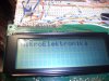
Lcd_Out(1,1,"electronics");
}
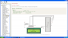
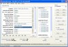
it is giving following error on build.

0 125 All files Preprocessed in 100 ms
0 121 Compilation Started lcd.c
5 313 Too many actual parameters lcd.c
6 324 Undeclared identifier 'Lcd_CLEAR' in expression lcd.c
0 102 Finished (with errors): 23 Jul 2009, 20:54:13 lcd.mcppi
please telll what is wrong.
 
You missed a part the part in red
Code:
[COLOR="Red"]char *text = "electronics";[/COLOR]

void main() {
  TRISB = 0;                // PORTB is output
  Lcd_Init(&PORTB);         // Initialize LCD connected to PORTB
  Lcd_Cmd(Lcd_CLEAR);       // Clear display
 [COLOR="Red"] Lcd_Cmd(Lcd_CURSOR_OFF);  // Turn cursor off[/COLOR]
  Lcd_Out(1, 1, text);      // Print text to LCD, 2nd row, 1st column
}//~!
 
Last edited:
...
5 313 Too many actual parameters lcd.c
6 324 Undeclared identifier 'Lcd_CLEAR' in expression lcd.c
...

I believe that is telling you that the constant Lcd_CLEAR is not recognised, I would try using LCD_CLEAR instead, or you can look in the file lcd.c and see how they defined it there..
 
hi guys finally i got the right program for mikroc pro ver2.25 which is atleast building

// Lcd pinout settings
sbit LCD_RS at RB0_bit;
sbit LCD_EN at RB1_bit;
sbit LCD_D7 at RB7_bit;
sbit LCD_D6 at RB6_bit;
sbit LCD_D5 at RB5_bit;
sbit LCD_D4 at RB4_bit;

// Pin direction
sbit LCD_RS_Direction at TRISB0_bit;
sbit LCD_EN_Direction at TRISB1_bit;
sbit LCD_D7_Direction at TRISB7_bit;
sbit LCD_D6_Direction at TRISB6_bit;
sbit LCD_D5_Direction at TRISB5_bit;
sbit LCD_D4_Direction at TRISB4_bit;

void main() {
Lcd_Init();

TRISB = 0; // PORTB is output
// Initialize LCD connected to PORTB
Lcd_Cmd(_LCD_CLEAR); // Clear display
Lcd_Cmd(_LCD_CURSOR_OFF); // Turn cursor off
Lcd_Out(1, 1, "electronics"); // Print text to LCD, 2nd row, 1st column
}//~!

but there is no result on lcd , lcd is only lightning
i m using 50 K pot.
please tell what gona wrong.
 
i use pic18f452 system with 4Mhz crystal , i also used 5k pot , dear please look on another program i made also not working


// LCD module connections
sbit LCD_RS at RD2_bit;
sbit LCD_EN at RD3_bit;
sbit LCD_D4 at RD4_bit;
sbit LCD_D5 at RD5_bit;
sbit LCD_D6 at RD6_bit;
sbit LCD_D7 at RD7_bit;

sbit LCD_RS_Direction at TRISD2_bit;
sbit LCD_EN_Direction at TRISD3_bit;
sbit LCD_D4_Direction at TRISD4_bit;
sbit LCD_D5_Direction at TRISD5_bit;
sbit LCD_D6_Direction at TRISD6_bit;
sbit LCD_D7_Direction at TRISD7_bit;
// End LCD module connections

char txt1[] = "mikroElektronika";
char txt2[] = "BigPIC5";
char txt3[] = "Lcd4bit";
char txt4[] = "example";

char i; // Loop variable

void Move_Delay() { // Function used for text moving
Delay_ms(2000); // You can change the moving speed here
}

void main(){

ADCON1 |= 0x06; // Configure AN pins as digital


Lcd_Init(); // Initialize LCD
Lcd_Cmd(_LCD_CLEAR); // Clear display
Lcd_Cmd(_LCD_CURSOR_OFF); // Cursor off

Lcd_Out(1,6,txt3); // Write text in first row
Lcd_Out(2,6,txt4); // Write text in second row
Delay_ms(2000);
Lcd_Cmd(_LCD_CLEAR); // Clear display

Lcd_Out(1,1,txt1); // Write text in first row
Lcd_Out(2,5,txt2); // Write text in second row
Delay_ms(2000);

// Moving text
for(i=0; i<4; i++) { // Move text to the right 4 times
Lcd_Cmd(_LCD_SHIFT_RIGHT);
Move_Delay();
}

while(1) { // Endless loop
for(i=0; i<7; i++) { // Move text to the left 7 times
Lcd_Cmd(_LCD_SHIFT_LEFT);
Move_Delay();
}

for(i=0; i<7; i++) { // Move text to the right 7 times
Lcd_Cmd(_LCD_SHIFT_RIGHT);
Move_Delay();
}

}
}


i dont think there is any comparator in pic18f452 system , b/s i hve seen some programs asking for turning off comparator. dear please solve this problem or send me any other working code , i atleast need to check my hardware.
 
einton try this out and see if you can get this going you have to gnd all unused pins like in the screen shot I zip the code you unzip it and run it
 

Attachments

  • LCD18F452SET.PNG
    LCD18F452SET.PNG
    122.7 KB · Views: 4,150
  • LCD18F452.JPG
    LCD18F452.JPG
    1.6 MB · Views: 1,330
  • LCD18f452.zip
    2.5 MB · Views: 1,196
thanx be80be thanx 4 ur code i could try it but i m working on mikroc pro , i initially try on mikroc but there was a problem of config bits in that ,so i left that, now using mikroc pro and atleast i know there is no problem of config bits , since i have tested. help on mikroc pro if possible.
 
It has the hex in the zip what programmer are you using and what do you mean
mikroc but there was a problem of config bits
I used a pickit2 and when it verified it would say can't read configure bits but that's because your using the lcd on that port. I would program chip and then hook rb7 and rb6 up to lcd and it works fine
 
thanx be80be
dear i have universal programmer which asks for writing config bits in its config bits window before programming chip, when using mikroc i copy bits from edit project ,but it didnt work as it work when i used to copy them from mplab , config bits in edit project in mikroc were also very different and it didnt work , when i use config setting in mikroc pro it did work , so i let start mikroc pro , if u know how can i set config bits in mikroc then tell please.
 
If you hook your LCD up like i showed you with the screen shot this works
Code:
  // LCD module connections
sbit LCD_RS at RB2_bit;
sbit LCD_EN at RB3_bit;
sbit LCD_D4 at RB4_bit;
sbit LCD_D5 at RB5_bit;
sbit LCD_D6 at RB6_bit;
sbit LCD_D7 at RB7_bit;

sbit LCD_RS_Direction at TRISB2_bit;
sbit LCD_EN_Direction at TRISB3_bit;
sbit LCD_D4_Direction at TRISB4_bit;
sbit LCD_D5_Direction at TRISB5_bit;
sbit LCD_D6_Direction at TRISB6_bit;
sbit LCD_D7_Direction at TRISB7_bit;
// End LCD module connections

char txt1[] = "mikroElektronika";
char txt2[] = "EasyPIC5";
char txt3[] = "Lcd4bit";
char txt4[] = "example";

char i;                              // Loop variable

void Move_Delay() {                  // Function used for text moving
  Delay_ms(500);                     // You can change the moving speed here
}

void main(){
  TRISB = 0;
  PORTB = 0xFF;
  TRISB = 0xff;
  Lcd_Init();                        // Initialize LCD

  Lcd_Cmd(_LCD_CLEAR);                // Clear display
  Lcd_Cmd(_LCD_CURSOR_OFF);           // Cursor off
  Lcd_Out(1,6,txt3);                 // Write text in first row
  Lcd_Out(2,6,txt4);                 // Write text in second row
  Delay_ms(2000);
  Lcd_Cmd(_LCD_CLEAR);                // Clear display

  Lcd_Out(1,1,txt1);                 // Write text in first row
  Lcd_Out(2,5,txt2);                 // Write text in second row
  Delay_ms(2000);

  // Moving text
  for(i=0; i<4; i++) {               // Move text to the right 4 times
    Lcd_Cmd(_LCD_SHIFT_RIGHT);
    Move_Delay();
  }

  while(1) {                         // Endless loop
    for(i=0; i<8; i++) {             // Move text to the left 7 times
      Lcd_Cmd(_LCD_SHIFT_LEFT);
      Move_Delay();
    }

    for(i=0; i<8; i++) {             // Move text to the right 7 times
      Lcd_Cmd(_LCD_SHIFT_RIGHT);
      Move_Delay();
    }

  }
}
and it's in microC PRO
 
Here a little video not real good but you can see how it works
[embed]http://www.youtube.com/v/vdww6_fM9L0&hl=en&fs=1&[/embed]
 
Same Problem

Hey einton / be80be,

I am interested to know if you resolved your issue.

I'm having similar issues with an 4x20 LCD and a PIC18LF4580.

I'm using mikroC PRO (09 version), and PICkit 2 programmer.

I've copied and pasted the sample code, tried both PORT A and B, tried using RB2-RB7 rather than the RB0-RB05 pins that are in the documentation. Tried 2 different PIC18LF4580, tested every wire and rebuilt the circuit several times just in case I couldn't see an obvious errant connection (forest from the trees type error).

The LCD lights up, the contrast adjustment works and I adjust the contrast I see that line 1 & 3 are solid. In fact this is the case if the PIC is not connected at all.

I am buggered if I can work out why I don't get any text on the screen.

Did you get yours working? if so, what was the fix?

It seams so simple, yet I've spent hours trying to work it out.

Any suggestions?

Cheers,

Doug.
 
Did you ground all unused pins on the LCD if not all you'll get is the is a bunch of square boxes when the LCD lights up
 
Yep, pins 1, 5, 7, 8, 9 & 10 on the LCD connector are all grounded.

My thoughts are:
a) I am selecting something wrong when saving the hex file (pic attached) or
b) LCD unit is faulty

The PIC controller is definately functioning, I have tested 2 units and other programs work fine.

I have made sure the power to the PIC is going through a regulator with 2 caps to make sure that its nothing to do with power. (I have heard of people having issues with PICs resetting if the Vdd is not isolated)

Is it possible that this particular PIC requires some other setting or code to get it to work?
 

Attachments

  • PicFlash_ screenshot.JPG
    PicFlash_ screenshot.JPG
    302.3 KB · Views: 621
Thanks Be80be and Rajbex,

I've monitored traffic on all the pins used and the screen is reacting. All I am getting is a row of blocks on row 1 and 3. It is flashing on and off every 2 seconds or so (as you would expect from the code that Raj linked above).

I think I've come to the conclusion that my LCD is buggered. I've sent for another couple.

It is most frustrating, but thanks heaps for your suggestions.
 
solution

hi guys finally i got the right program for mikroc pro ver2.25 which is atleast building

// Lcd pinout settings
sbit LCD_RS at RB0_bit;
sbit LCD_EN at RB1_bit;
sbit LCD_D7 at RB7_bit;
sbit LCD_D6 at RB6_bit;
sbit LCD_D5 at RB5_bit;
sbit LCD_D4 at RB4_bit;

// Pin direction
sbit LCD_RS_Direction at TRISB0_bit;
sbit LCD_EN_Direction at TRISB1_bit;
sbit LCD_D7_Direction at TRISB7_bit;
sbit LCD_D6_Direction at TRISB6_bit;
sbit LCD_D5_Direction at TRISB5_bit;
sbit LCD_D4_Direction at TRISB4_bit;

void main() {
Lcd_Init();

TRISB = 0; // PORTB is output
// Initialize LCD connected to PORTB
Lcd_Cmd(_LCD_CLEAR); // Clear display
Lcd_Cmd(_LCD_CURSOR_OFF); // Turn cursor off
Lcd_Out(1, 1, "electronics"); // Print text to LCD, 2nd row, 1st column
}//~!

but there is no result on lcd , lcd is only lightning
i m using 50 K pot.
please tell what gona wrong.


include the library file for lcd...you can also ground th Vee pin in the lcd...
 
Plz can anyone help me
when i use this to defined portd on PIC16F877A I've got an error
// 1- Comments :
/* Name: LEDS Light Chaser with multi modes
MCU: PIC16F877A 4MHZ
*/

// 2- Definitions
/* */
sbit led0 at portd.f0; //This is where led0 is fully defined
sbit led1 at portd.f1; //This is where led0 is fully defined
sbit led2 at portd.f2; //This is where led0 is fully defined
sbit led3 at portd.f3; //This is where led0 is fully defined
sbit led4 at portd.f4; //This is where led0 is fully defined
sbit led5 at portd.f5; //This is where led0 is fully defined
sbit led6 at portd.f6; //This is where led0 is fully defined
sbit led7 at portd.f7; //This is where led0 is fully defined

// 3- Variables Declaration

unsigned int count; // for loop event loop

// 4- Main Function

void main()
{
// a- Port Initialization

trisd=0x00; // all pins of portd as output
portd=0b00000000; // Initialy clear port

//b- Form an endless loop

while(1)
{
for(count=0;count<10;count++) // repeat 10 times the following as patern 1:

{ // forward from led0 to led7
led0=1;
delay_ms(250);
led0=0;
led1=1;
delay_ms(250);
led1=0;
led2=1;
delay_ms(250);
led2=0;
led3=1;
delay_ms(250);
led3=0;
led4=1;
delay_ms(250);
led4=0;
led5=1;
delay_ms(250);
led5=0;
led6=1;
delay_ms(250);
led6=0;
led7=1;
delay_ms(250);
led7=0
}
}
}

the error is : ';' expected but led0 found
& in the same row an error: Internal error

I need help

Thanks.
 
Last edited:
Status
Not open for further replies.

Latest threads

New Articles From Microcontroller Tips

Back
Top