Continue to Site

Welcome to our site!

Electro Tech is an online community (with over 170,000 members) who enjoy talking about and building electronic circuits, projects and gadgets. To participate you need to register. Registration is free. Click here to register now.

  • Welcome to our site! Electro Tech is an online community (with over 170,000 members) who enjoy talking about and building electronic circuits, projects and gadgets. To participate you need to register. Registration is free. Click here to register now.

microwave transformer

Status
Not open for further replies.

quinnbrian

New Member
I have some questions on using a microwave transformer as an invertor.I found the diagram and have all the pieces required.My questions:
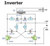
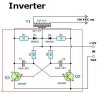
will the diagram below make 15 Amps of 120?
or will i needed to upgrade some of the parts?
I read the constrution remarks on building /using the microwave transformer (as T1 in the diagram) but still am not quite clear on how to build it .I know that you have to remove the 2000 v secondary and rewinded it with 12 turns of heavy wire and twist a loop (center tap)and then 12 more.But I don't know how heavy the wire should be and what is a center tap? My transformer has a primary winding,a field winding,and a secondary winding.do I just remove the field winding? OR??
Any help would be greatly appreciated.
 

Attachments

  • inverter_648.jpg
    inverter_648.jpg
    19.1 KB · Views: 2,558
If you need 120 Volt x 15 Amp. (=170 Volt piek) The 2N3055 has to supply 14 x 15 Amp ( 1/2 wave) if the inverter should work at 100 % eff.
2N3055 is not able to supply 200 Amp ! Maximum 10 A piek.
 
took a look at the web page,little more work than I want to get into right know.I'd like to uses what I've got.If I make a multiable input Say 5 or 10 of them would this work? Below (with the red box around it) is the parts of the diagram that I would make 5 or 10 of and just hook them up in (stack them) on top of each other.What do you think?
 

Attachments

  • inverter22.JPG
    inverter22.JPG
    21 KB · Views: 2,072
quinnbrian said:
took a look at the web page,little more work than I want to get into right know.I'd like to uses what I've got.If I make a multiable input Say 5 or 10 of them would this work? Below (with the red box around it) is the parts of the diagram that I would make 5 or 10 of and just hook them up in (stack them) on top of each other.What do you think?

To be honest I don't think even the version as it's shown (but with a 50-100W transformer) is going to work anyway - it's far too crude. An inverter relies on accurate switching on and off of the output devices, preferably with a short gap while both are turned off - transistors don't turn off instantly, and turning one on before the other is completely off is a recipe for disaster.

You couldn't just duplicate the components in the red box, all the multivibrators would run at different frequencies - things would go BANG! big style!.

The way to parallel it up would be to simply parallel transistors across the existing ones, with each transistor having it's own low value emitter resistor to ensure load sharing. However, the existing 180 ohm resistors wouldn't be able to supply enough base current for all the transistors, so would need reducing substantially - then the oscillator frequency would be wrong, requiring the capacitors changing.

A self oscillating design isn't a good idea, and as I mentioned I'm doubtful it would work at all. A seperate oscillator feeding the output stages via drivers would be a better bet - preferably designed to arrange that both transistors are off before the next one is switched on.

The design on the web link that 'looks a little complicated' looks pretty reasonable to me - anything dealing with these sorts of powers will destroy all the expensive bits very, very, easily - a lot of the circuitry is to help prevent that.

I presume you are aware of the current something like this is going to take off 12V? - probably getting up towards 200A!.
 
Nigel,the web site I got the diagram from is www.aaroncake.net/circuits/inverter.htm could you take a look at it and give me any input .Thanks alot for your input on the above posting.I'm new to this type of thing and when I seen this diagram ,thought it would be a good first inverter project.After reading the web.site again it says the inverter CAN be construted to supply any where from 1 to 1000 watts and then down the page a little more it says that by using the parts in there parts list that the inverter can only supply 300 watts. :oops: Thanks again and I will take another look at the web site you have provided.
 
quinnbrian said:
Nigel,the web site I got the diagram from is www.aaroncake.net/circuits/inverter.htm could you take a look at it and give me any input .Thanks alot for your input on the above posting.I'm new to this type of thing and when I seen this diagram ,thought it would be a good first inverter project.After reading the web.site again it says the inverter CAN be construted to supply any where from 1 to 1000 watts and then down the page a little more it says that by using the parts in there parts list that the inverter can only supply 300 watts. :oops: Thanks again and I will take another look at the web site you have provided.

I've had a look at the link, I see where you got the 15A from now - it's the the rating of the 24V winding, not the 120V one :lol:

It also says at the bottom, that it's very tricky to get working, and I can't say I'm surprised. When you design anything, it should be easily reproducible - that design certainly isn't.
 
Nigel Goodwin said:
quinnbrian said:
Nigel,the web site I got the diagram from is www.aaroncake.net/circuits/inverter.htm could you take a look at it and give me any input .Thanks alot for your input on the above posting.I'm new to this type of thing and when I seen this diagram ,thought it would be a good first inverter project.After reading the web.site again it says the inverter CAN be construted to supply any where from 1 to 1000 watts and then down the page a little more it says that by using the parts in there parts list that the inverter can only supply 300 watts. :oops: Thanks again and I will take another look at the web site you have provided.

I've had a look at the link, I see where you got the 15A from now - it's the the rating of the 24V winding, not the 120V one :lol:

It also says at the bottom, that it's very tricky to get working, and I can't say I'm surprised. When you design anything, it should be easily reproducible - that design certainly isn't.

I agree with Nigel, I can smell the burning transistors already. To answer your earlier question, there are transistors that can support 200A but your will need several amps of base current. The original schematic is not a very robust design. If you are going to re-design that circuit (not recommended for first timers), I would consider using power MOSFETS instead, it will be much easier to drive the gates. Oh and I wouldnt do that self-oscillating thing that will be sensitive to all kinds of things including the phase of the moon(JK).

A simple digital circuit can provide clean predictable gate drive signals.

Just my .02
 
Status
Not open for further replies.

Latest threads

New Articles From Microcontroller Tips

Back
Top