Continue to Site

Welcome to our site!

Electro Tech is an online community (with over 170,000 members) who enjoy talking about and building electronic circuits, projects and gadgets. To participate you need to register. Registration is free. Click here to register now.

  • Welcome to our site! Electro Tech is an online community (with over 170,000 members) who enjoy talking about and building electronic circuits, projects and gadgets. To participate you need to register. Registration is free. Click here to register now.

mic to speaker circuit

Status
Not open for further replies.

twingesabit

New Member
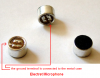
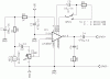
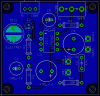
I"m working on designing a project utilizing a closed loop mic/speaker circuit. I'm using a design based on the LM386. I've populated the board and checked for any errors in placement but so far so good. However, when powers applied I'm getting a low frequency oscillating feedback. Following the schematic, I'm getting a solid feedback and if I place a diode between Pin 4 and speaker GND (to block feedback), the signal changes to AC (presumably) and creates a rising/falling type oscillation (signal valley isn't being heard, it just turns off then picks back up while cresting). Forgive some of the terminology, I deal with DC mostly. All components were sourced from Radio Shack. All caps are 35V (excessive given the 9V circuit, but it was the only thing available locally). I've tried a few different variations in teh circuit (diode placement) but would appreciate any feedback. Mic is electret condensor PC mount type, Speaker is standard 8 ohm speaker. Regards.
 

Attachments

  • LM386 with mic.PNG
    LM386 with mic.PNG
    13 KB · Views: 567
The circuit looks ok to me.

Please recheck the polarity of the electrolytic capacitors.

Boncuk
 
All the caps are positioned properly. However, would that cause the oscillation that I'm experiencing? I'd think it would just block the circuit if the polarity were reversed.
 
I'm getting a low frequency oscillating feedback

First you complain about feedback

would appreciate any feedback

Then you ask for feedback?

its easy to get confused here

Sounds to me the mic is to close to the speaker and with the gain of the amp it will have feedback.

Move the mic and speaker further apart and see if that fixes the problem.
 
Last edited:
Temporarily disconnect the mic, and see if you still hear the oscillation in the speaker?
 
Currently I'm using the gain increase that the schematic calls for, but I can remove that and use the low end gain the op amp provides for now. My design area is limited and I'm not concerned with quality of the output as long as it's capable of sensing something. In theory I'd like this to perform like a looped telephone. I want to be able to hear whatever I'm saying into the mic, however, given the simplicity of the circuit, is this even possible? Thanks.
 
I want to be able to hear whatever I'm saying into the mic, however, given the simplicity of the circuit, is this even possible?
It is not possible unless you wear headphones that completely cover your ears so they are sealed. Or record it, turn off the mic and play it back.
If you can hear the speaker then the mic can also hear the speaker. Then the sound goes around and around causing acoustic feedback howling. Maybe the low frequency feedback you hear now is acoustic feedback.
 
Thanks for the replies, i'm going to see if I can't tweak the circuit a bit to meet my goal. Might have to just run the amp output to a 3.5 jack and use some headphones lol.
 
As a side note... I did disconnect the mic and still received the feedback... so there seems to be some error in my placement but what could be causing the speaker to react like that?
 
You should make a very careful check to see that you have not made some mistake in your circuit.

Unfortunately, the physical layout of the circuit is also very important for this sort of project. This may be hard for you to get right if you have not done much of this sort of thing before.

There are some general rules, like keeping input and output circuits away from each other. The microphone should be connected using screened cable: the outer conductor of the cable goes to ground, the inner conductor goes to the input.

Generally connections should be no longer than necessary. Decoupling capacitors (like the 470uF on your +9V input to pin6) should be close to the IC.

You should use separate wires to connect the negative of the battery to the amplifier, and the ground side of the speaker to the amplifier. The ground side of the microphone should be connected using the screen of its own cable as above. Do not use one wire for more than one of these connections, as this can lead to feedback due to the slight resistance (and even inductance!) of the wire.

If all this proves too difficult, one way of getting round this may be to build a kit using a pre-designed PCB.
 
Thanks for the info... I haven't built circuits of this type before but I'm aware of cable inductance and other such issues.. one of my primary concerns when i first started the project was whether or not there would be an issue with induction... since my design is in such an enclosed space would it be beneficial to place shields around the separate circuits to further isolate any noise? I've been tinkering with the design and by using an ext. audio jack I'm not getting the pulsating buzz I had before.. now it sounds more like the squelch on a CB radio. Also, should I use a shielded speaker to reduce any potential noise that the magnet might create? Thanks for the info.
 
As a side note, cell phone have the speaker on the opposite side of the mic to avoid feedback.
That helps only a small amount.
All cell phones that I have seen and most cheap speakerphones operate in half-duplex to avoid acoustic feedback howling. The half-duplex circuit attenuates the speaker when you speak into the mic and attenuates the mic when the speaker is playing sounds from the other end. Frequently half-duplex with background noises cuts-off people's voices.

Very expensive boardroom teleconference speakerphones use a digital echo canceller that makes and remembers a model of the acoustics in the room and it cancels its speaker sounds and room echoes from its microphone. It also cancels its mic sounds from its speaker including long distance echoes in the telephone lines.

Since the problem still occurs with the mic disconnected then the only place where feedback can come from is the power supply. The 470uF capacitor across it and/or the 100uF capacitor that filters the mic supply voltage might be open or missing.
 
Thanks for the info... I haven't built circuits of this type before but I'm aware of cable inductance and other such issues.. one of my primary concerns when i first started the project was whether or not there would be an issue with induction... since my design is in such an enclosed space would it be beneficial to place shields around the separate circuits to further isolate any noise? I've been tinkering with the design and by using an ext. audio jack I'm not getting the pulsating buzz I had before.. now it sounds more like the squelch on a CB radio. Also, should I use a shielded speaker to reduce any potential noise that the magnet might create? Thanks for the info.

The field from the magnet is unlikely to be an issue, although coupling from the voice coil and its wiring might be. You probably should return the speaker frame to common, and if you are building this thing in a metal box that should be returned to common as well.

It may just be a question of screening, but you need to be sure that there is not something more basic wrong first, such as a wiring mistake or a faulty component. I would recommend you first to try out the circuit on a table, with the loudspeaker well away from the board, to see how it works. If you manage to get it going properly like that, then try putting it back into its cramped container. That way it should be simpler to tell if you really need more screening. It is always better to do things in easy stages.
 
Some success... I changed the 470uF and the 100uF with some spares I had around the house... now I'm getting audio throughput consistently (not the best quality, but consistent). The mic sensitivity doesn't seem very impressive though, I have to be right on top of the mic in order for it to pick up anything. Could I add a preamp circuit designed around teh same LM386?
 
The LM386 set for a gain of 200 has plenty of gain for an electret microphone. Maybe your microphone is not an electret, it might be a dynamic mic (coil and magnet) which does not need to be powered to work. The resistor that powers an electret mic might cause a dynamic mic to have low sensitivity. If the wires on an electret mic are connected with backwards polarity then the sensitivity might be reduced. The metal case terminal should be connected to the circuit's 0V (ground).
The LM386 should produce almost perfect quality.

The LM386 is a power amplifier that has plenty of hiss. If you want a preamp then use a low noise opamp circuit.

Here are photos of a two-wire electret mic. Some electret mics have three wires and need to be connected differently.
 

Attachments

  • electret mic2.PNG
    electret mic2.PNG
    214.1 KB · Views: 574
Hi twingesabit,

building an amplifier circuit on a breadboard might be problematic because of many unshielded and long wires.

Here's the circuit design with a small add on - a switch to select gains of 50 and 200.

The traces are short and the ground fill takes care of no unwanted feedback.

Boncuk
 

Attachments

  • LM386-SCH.gif
    LM386-SCH.gif
    18 KB · Views: 444
  • LM386-BRD.gif
    LM386-BRD.gif
    22.8 KB · Views: 437
Thank you for your response. That's more than I could have asked for. I"m going to look into the circuit a little more and determine what's causing my sensitivity issue. The mic is an electret though and the polarity is correct, however I may have an issue with my volume selection circuit, I'm looking for another pot to put in just in case. The first one was something I had laying around and my not be optimal.

Boncuk, do I have permission to use the PCB schematic you provided. It looks like it would be ideal for my application. Also, can anyone suggest a place to have the board propagated, maybe just as a sample to begin with? I appreciate all the help and I'll be sure to help out as well whenever I can. Regards.
 
Hi twingesabit,

getting the PCB made at a PCB manufacturer might turn out a bit expensive. They normally ask for a minimum board size to carry out an order.

This layout measures 45.0850X43.8150mm (1.7750X1.7250")

May be one of your friends runs Eagle. He might print the PCB layout on matching material for toner transfer onto a copper clad.

Of course you have permission to use the PCB layout. That was it's purpose.

To make it easy I attached the schematic and PCB design as a zip file.

Regards

Boncuk
 

Attachments

  • LM386.zip
    10.2 KB · Views: 242
As an update... using the board layout that Boncuk provided I was able to resolve my problems. At this point the pickup on the mic is extremely sensitive and has resulted in temporary deafness. I've adjusted the gain down to the 20 as provided by the op amp but would like to make this an adjustable value. 200 will work in certain situations but for the most part I'd be looking at a range of 80-150 for my application. Would using a trimmer cap accomplish this? If so, what value would I need to look at. Regards.
 
Status
Not open for further replies.

Latest threads

New Articles From Microcontroller Tips

Back
Top