Continue to Site

Welcome to our site!

Electro Tech is an online community (with over 170,000 members) who enjoy talking about and building electronic circuits, projects and gadgets. To participate you need to register. Registration is free. Click here to register now.

  • Welcome to our site! Electro Tech is an online community (with over 170,000 members) who enjoy talking about and building electronic circuits, projects and gadgets. To participate you need to register. Registration is free. Click here to register now.

Measuring mains voltages / currents / (frequency) with a PIC

Status
Not open for further replies.
I have got the PIC reading several analogue inputs and sending the data up the serial to a PC. My next problem is the high voltage part - I've come up with some circuits for the current measurement but is there any problems with doing it this way or is isolation required?

If I'm measuring more than one current (through an appliance) would the common ground be a problem?
 

Attachments

  • unisolated mains current measure.jpg
    unisolated mains current measure.jpg
    21.9 KB · Views: 801
  • isolated mains current measure.jpg
    isolated mains current measure.jpg
    25.7 KB · Views: 628
Your first circuit is highly dangerous, please dont use it!
There is no isolation form the mains.

I suggets that you use a small mains transformer to provide isolation and transform the 240v down to 12v or so.
Then rectify and scale the to give the require reading on the PIC.

The second circuit may work, but is rather unconventional, using a resistor/transformer like that.
To measure current, I suggest you use a current transformer.
Have a look here for a few examples:
Process Control | Sensors and Transducers | Current Transducers

JimB
 
I was looking at current transformers but I was put off because they seem very inaccurate, I had a home energy monitor with a current transformer sensor and it never read what the actual power being used was, hence I want to build one myself. It was always over by quite a lot, I guess the manufacturer made it that way so as to scare people into using less electricity, but it doesn't work with me as I don't believe two lights and a computer equate to 1kW. Moving the position of the current transformer on the cable changed the reading considerably and the clip was too big for cable, it was loose. Also, I can't break the 100A cable coming into my house to get sensor round it. Ideally I was thinking I needed to have an in-line shunt to measure current accurately at low currents.

I want to log current readings from normal appliances to a computer to see, for example if the fridge/freezer is cycling on too much and what time of day the most power is used. A 15Amp current transformer seemed overkill anyway.

Will current transformers work on a two or three wire flex? I thought they only work on single cable as the return cancels out.
 
Inserting a CT does require disconnecting/reconnecting just one of the wires going to the load, usually the line with 120V/240V on it. In the US, you can buy a **broken link removed** break it open, and you have a nice CT for experimenting.
 
Last edited:
I was looking at current transformers but I was put off because they seem very inaccurate,
Current transformers are used in many places in industry where a mains supply current is to be measured. They are accurate enough, far better than what you have experienced.


I had a home energy monitor with a current transformer sensor and it never read what the actual power being used was, hence I want to build one myself. It was always over by quite a lot, I guess the manufacturer made it that way so as to scare people into using less electricity, but it doesn't work with me as I don't believe two lights and a computer equate to 1kW. Moving the position of the current transformer on the cable changed the reading considerably and the clip was too big for cable, it was loose.
That equipment was obviously a piece of junk.
Moving a current transformer (CT) should not make the reading vary.
Most CTs have a hole which is far bigger than the cable.

Also, I can't break the 100A cable coming into my house to get sensor round it. Ideally I was thinking I needed to have an in-line shunt to measure current accurately at low currents.
OK, if you cant break the cable to put a CT, where will you connect the shunt resistor?
It is possible to buy CTs which split open to go around a cable which cant be broken, but they will probably be expensive for your application.

I want to log current readings from normal appliances to a computer to see, for example if the fridge/freezer is cycling on too much and what time of day the most power is used. A 15Amp current transformer seemed overkill anyway.
I dont think a 15A CT is all that OTT, you can change the sensitivity by varying to load resistor on the output of the CT.

Will current transformers work on a two or three wire flex? I thought they only work on single cable as the return cancels out.
No they wont, the magnetic fields from the line and neutral wires cancels out and the reading will be zero.
This is how an earth leakage circuit breaker (ELCB)* works by detecting the imbalance in the phase and neutral currents.

* Now more usually known as a Residual Current Circuit Breaker (RCCB) in the UK or a Ground Fault Interuptor (GFI) in the USA.

JimB
 
Would a 16A / 32A circuit breaker be the same as a RCD / GFCI in containing a CT?
Probably not.
Depending on the circuit breaker, there may be a thermal trip and a magnetic trip, but this is just a coil of wire pulling on an iron core, not a CT.

JimB
 
What do you want the max current to be and what do you expect to spend? The link JimB provided had some nice options including split core CT so you would not have to disconnect the mains. I assume 220 Volt mains?

Ron
 
Simplest thing for voltage is to use a 6.3vac or 12.6v step down transformer.

Hall effect sensors are good for current measurements. There are open loop and closed loop hall effect sensors. A closed loop sensor is generally more accurate. It uses a second coil on the torroid driven by a feedback amplifier to create a counter magnetic field that drives the magnetic bias on the core to near zero eliminating most of the magnetic core non-linearities versus magnetic bias level.

Some low cost open loop sensors are Allegro sensors.

When doing rectification be aware of the diode drop voltage. A bridge will chop off about 1.2 volts and will produce near zero if the signal is so low as to not even turn on diodes. A op amp feedback rectifier can solve this issue.

If you are trying to catch things like motor startup surges you need to pay attention to frequency response of current sensor. 100kHz to 300 kHz Hall effect sensors are commonly available. Cheap current loop transformer sensors are inherently slow.

Finally, do you want true R.M.S. or simple averaging value of AC? If dealing with relatively constant 60 Hz sinewaves you can get by with R-C averaging and scale output to equivalent R.M.S. value. If you are trying to calculate power factor you need to be aware of delays that may impact timing relation between current measurement and voltage measurement.
 
Last edited:
Initially I was going to build a circuit which is more accurate than the energy monitor I currently have because my dad looks at the monitor and immediately turns red with anger at how much energy I'm using. But I've disconnected everything, then plugged just the PC or lights on with an ammeter in series to show the monitor is way off.

I want to build something that can measure the total energy consumption of the house on the live cable coming in (which cannot be broken for safety and legal reasons) and also to measure small appliances power usage throughout the day to see what's on and when.

Ideally I didn't want to spend anything (as usual), I have loads of components from things I've taken apart over the years and hoped to build something with them. I was thinking to build the latter first because that seems easier to use a shunt and transformer.

Is there anything inherently wrong with the transformer across a shunt resistor - sensitivity, accuracy, isolation, etc? I was going to put a 12v 500mA transformer with the low voltage side across the shunt to boost the voltage and minimise the diode drop in the bridge.

The maximum current for measuring on the single appliance I can imagine will be 5 amps unless a fridge/freezer draws way more than that starting the motor? The whole house measurement will need to be capable of 30Amps or more as the cooker and microwave are powerful.

I've given up trying to measure voltage because it seems redundant as it will not change much.
 
First, measuring power using I * V will not tell you the whole story. If we look at the power consumption of your parents home and measure the mains voltage and multiply that by the current we will get apparent power which is not the true power. You need to take into account the power factor. This may be why what you see and the power meter don't agree.

Next, if you want to measure mains voltage and current accurately (discounting power factor at this point) you really need to go with a good voltage transducer that will measure the mains voltage, scale it down and output an accurate usable signal to your PIC or recording device. That involves considerable signal conditioning for example to monitor 0 to 300 VAC 50 Hz. mains and scale that to either 4 to 20 mA or 0 to 5 volts as a useable signal. The same holds true for the current, again scaling to a usable output. Typically an accurate current transducer is used with outputs much like I already mentioned. Devices like these aren't cheap and are not easily fabricated from misc. scrap parts. You can't have free or cheap in the same sentence with accurate. :(

Exactly why do you feel the power meter is inaccurate? Have you considered the PF? I can't speak for UK power meters on their grids but here in the US I have found mine to be pretty accurate. Especially the new electronic versions they are installing.

A slick device for use on single appliances etc. here in the US is the Kill-A-Watt power meters sold for about $20 USD. I don't know if they have ever come out with a 220 volt 50 Hz. Euro version yet.

Ron
 
Last edited:
Firstly, I agree with everyone else that for safety, measure the current and voltage through transformers. Ordinary mains transformers are fine to measure the voltage, as long as the transformer load is near zero. You just have to remember that a 6 V transformer is 6 V RMS under full load, and so about 8 V RMS, and 12 V peak, unloaded. However, if you don't load it, it's ratio (say 230:8 in this example) won't change.

Where I used to work, we had a 3 MW, 11kV motor. It had it's own electricity meter, that looked just like a domestic one. If you looked closely, you could see that the numbers were larger, and there were 6 wires. Looking very closely, you could see the voltage and current transformer ratios that it was calibrated to. I think it was on 100:1 voltage, and I guess the same for current, so the power it measured was 300 W, and it wouldn't have absorbed even that much power. My point is that you don't need to measure the scary voltages directly to get the right readings.

Also, don't rectify before measuring. A PIC is plenty fast enough to measure many times during a 50 Hz cycle, so you can measure the power factor and frequency just as easily. Almost all loads will have a power factor less than one, and many modern appliances have very strange current waveforms, so assuming that they are sinewave is a massive inaccuracy.
 
I've connected the transformer across the mains inputs to measure the voltage but it's not very accurate - about 1V resolution. Is there a way to measure only the top 5V or 10V at the high end. I'm using the most significant 8 bits of the 10 bit ADC register and I know that I will lose resolution with less bits?
 

Attachments

  • mains voltage measurement.jpg
    mains voltage measurement.jpg
    63.2 KB · Views: 335
Last edited:
Why aren't you using the last 2 bits? You could just use the least significant 8 bits of the 10 bit ADC. If you scale it to give full scale at 280 V rms, then losing the first 2 bits means that you won't know if the voltage is 0 - 70, 70 - 140, 140 - 210 or 210 - 280. However, you are measuring UK mains so the last one is the only realistic possibility. That way you have an 8 bit register representing 210 - 280 V with a resolution of 0.273 V.

The other possibility is to measure with a centre-tapped secondary, and no rectifier. Then you measure the positive and negative peaks separately. That gives you peak to peak range of 11 bits (two lots of 10 bits added together) and you can measure phase and waveform if you want. The zener circuit that you have will protect the PIC against the negative input voltages.
 
Hi,


Current transformers are not too bad really, but may be a little nonlinear toward the low end.
Hall effect sensor IC's are fairly cheap these days and work up quite high.
Sense resistors are also used with amplifiers to amplify the voltage across the resistor and this keeps the series value down low.

With any of these despite the inaccuracies you can 'calibrate' them by simply running a known current through them and measuring the output. You can then set up a scale factor/curve to get more accuracy.
For example, say we run currents of 1,5, and 10 amps through the device and we get as a response 1.1, 5.5, and 11 volts. We can see that we have a scale factor of 1.1 so we simply divide each output by 1.1 to get the 'real' input.
Sometimes it isnt that easy though, say we use the same test currents 1,5, and 10 again, but this time we read 1.0, 5.5, and 10 volts as outputs. Now there is no single scale factor that works for all readings so we have to use linear interpolation, or to get more accuracy we can use a curve fitting strategy.
 
Last edited:
Something to consider is no matter how you slice it and dice it from a simple standpoint if you scale 0 to 250 Volts to let's say 0 to 5 volts you have a 50:1 ratio. Simply put with 8 bit A to D conversion you end up with 250 being divided down into 256 (8 bit) quantization levels. That gives you 250 / 256 = 1.024 or a best case resolution of about 1.024 volts.

Ron
 
Hi Ron,


Oh yes, very good point.
On another related note, the resolution of 1v might not be good enough, but we dont want to have to move to a higher resolution ADC. What to do?
Well, the standard measurement technique is mostly linear, but if we move away from a purely linear measurement technique we can get higher resolution provided the range of input measurment is restricted. For example, the line itself can range from 0v to 140v roughly which is a range of 140v, but most of the time the line is from 80 to 140 volts, which is only a range of 60v. Using a subtract circuit or other non linear circuit we can subtract 80v from the 0 to 140v line which gives us range of 0v to 60v which represents the line being 80 to 140 volts.

A simpler example using an 8 bit ADC though is this:
Say the line is 0 to 256v. Using a standard linear technique we get 1 bit per volt, which is a resolution of 1 volt. But this line only varies from 128v to 256v. That's a cut in the range by 50 percent, and now if we subtract 128v from the 0 to 256v line we get 0 to 128v, which represents 128v to 256v. Now we get a better resolution of 0.5 volts.
To put it another way, with the pure linear technique we might measure 128v or 129v, but we cant measure 128.5v. With the subtractor, we can measure 128v but also 128.5 volts, and of course 129v.

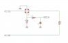
In a real circuit we might divide down the 0 to 256v to 0 to 10v, then subtract 5v, or perhaps divide down to 0 to 5v, subtract 2.5v, then amplify by 2 to get back to 0 to 5v which represents 128v to 256v.
The disadvantage of this technique is that we can no longer measure voltages below 128v, but we did it knowing that we would never have to. If necessary though, we could call 128v an 'under-range' voltage and trigger an error or alarm.
 
Last edited:
Hi Ya MrAl, Oh I agree completely. I don't know the normal range for 220 VAC european mains but all that should be of concern is 220 +/- a small amount. I know my typical line voltage is 123.5 VAC and I seldom see it below 122 or above 124 VAC. Using the method you propose is the only way to get really nice resolution with what there is to work with.

Ron
 
Hi again Ron,


Yeah i was just trying to help a little just in case someone wanted a little more resolution for the buck (dollar). It may be a little harder to achieve, but some circuit applications might benefit greatly.
 
Status
Not open for further replies.

Latest threads

New Articles From Microcontroller Tips

Back
Top