Continue to Site

Welcome to our site!

Electro Tech is an online community (with over 170,000 members) who enjoy talking about and building electronic circuits, projects and gadgets. To participate you need to register. Registration is free. Click here to register now.

  • Welcome to our site! Electro Tech is an online community (with over 170,000 members) who enjoy talking about and building electronic circuits, projects and gadgets. To participate you need to register. Registration is free. Click here to register now.

Measuring input voltage

Status
Not open for further replies.

EngIntoHW

Member
Hi,
I'd like to connect 9v battery to the Vin input of the Arduino Uno.
I'd also like observe in code when the battery level reaches below 7.5V so i know it should be recharged.
How can i do it efficiently without consuming too much power from the battery?
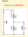
I thought maybe using two large equal resistors, connected in parallel to the battery, and connect the point between the two resistors to the Arduino Uno ADC input.

Would you suggest a more elegant way?

Thanks a lot. :)
 
A simple V divider, with high valued R's, fed to Arduino ADC would suffice.
You might want to add a cap to ground at ADC input as well because using
high valued R's makes input subject to noise pickup.

You could easily do this where divider only takes a uA or two.


Regards, Dana.
 
Some considerations :

1) Input leakage I/O pin is 1 uA, but ADC input states input R is 100 Meg. Not exactly
clear whaich is dominant spec...but I will use 100M

2) Vref is ~ 10%, so lets use AVcc and a 5% or better regulator for chip Vcc. Double check reg used on board, its specs.

3) Max 9V duracell battery V, no actual spec but graphs seem to indicate 10V number safe.

4) So min Vcc on chip = Vref = 4.9V per NSP117 spec. Therefore divider must present from 10V a max of 4.9V.
Closest standard values would be 1 M ohm.

1638887460383.png


Witch respect to (1) above if leakage is dominant you would see an offset of 1 ua thru 1 M = 1 V,
so check with a DVM, just to make sure you do not have a large error term due to leakage. Do
this with just R2 in circuit.


For cap I would think .01 uF ceramic disk adequate.

Layout make divider close to chip, no long lead runs from battery to divider to minimize noise pickup.


Regards, Dana.
 
Last edited:
While Danadak is partially right, the input impedance isn't the only issue, and Atmel/Microchip suggest a maximum source impedance of only 10K for the AVR in the Arduino. This is due (just at with a PIC) to the sample and hold capacitor, which needs to charge/discharge through the source impedance.

As long as you're only using one analogue input, you 'should' be OK but the datasheet suggests accuracy may be poor. This is why suggested circuits use an opamp buffer to give a high input impedance and a suitable low output impedance to feed the processor.

Other than that, for multiple analogue inputs, introducing long delays after switching input pins and before reading it, helps but still has the potential lack of accuracy issues.

I generally either use an opamp buffer (MicroChip do some nice low voltage rail to rail ones), or more often (as it's often in place anyway) is to monitor the battery voltage after a MOSFET switch feeding the voltage regulator.
 
A simple solution is to add a small cap, eg. 100nF, on the output of the divider, so the sample & hold cap charges from that, with little effect, rather than directly from a high impedance divider.

Add a 1K resistor and/or a schottky diode from the cap to the IC supply, so the cap does not discharge with excess current via the input pin when the device is switched off.
 
The RC time constant, X 5, is 50 mS for a 1Meg and .01 uF. If you are detecting
battery V drop as goal thats probably more than enough time for battery changes,
hence A/D settling time in its S/H in A/D front end. This not knowing if your loads vary
considerably over short periods of time. If the loads do then RC becomes a problem,
otherwise I think its ok to use the 1Megs.

The series R recommendation is dependent on how the supply collapses, in this
case the battery. So it may not be necessary, but JRW's comments very prudent.
When working with CMOS if you have large caps hung on pins, and the supply
pin is suddenly grounded, the discharge current from a cap can potentially damage.
If on the other hand the supply collapses by disconnect and drawing remaining
charge out of bulk caps maybe not of concern. Measurements would be prudent.


Regards, Dana.
 
Hi
Thanks a lot for the great help!
I used Dana's suggestion of the
R1 = 1.04Mohm
R2 = 1Mohm
Cext = .01microF

It worked great! No noise issues :)
 

Attachments

  • 1638887460383.png
    1638887460383.png
    36.5 KB · Views: 250
Status
Not open for further replies.

Latest threads

New Articles From Microcontroller Tips

Back
Top