Continue to Site

Welcome to our site!

Electro Tech is an online community (with over 170,000 members) who enjoy talking about and building electronic circuits, projects and gadgets. To participate you need to register. Registration is free. Click here to register now.

  • Welcome to our site! Electro Tech is an online community (with over 170,000 members) who enjoy talking about and building electronic circuits, projects and gadgets. To participate you need to register. Registration is free. Click here to register now.

Meassure current up to 70A DC

Status
Not open for further replies.

Kryten

New Member
Hi. This might be some where on the forums here but i couldnt find it anywhere.

Im going to make a power monitor for a 12VDC windmill and batterybank. For the output i need to meassure about 70A (ca 60A max load). does anybody have any ide as to what setup to use?

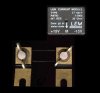
I've looked at using a shunt resistor but are afraid it might be too much power going out for it.

regards from Norway
 
A current shunt (low value resistor) will be fine.
You just need to make the resistance low enough so that the volt drop acress the shunt, and hence the power dissipation is not too high.
I have a commercialy built 50A shunt which gives 50mV at 50A, so its resistance is 1mOhm.

JimB
 
Hy Kryten,

It may sound a bit funny but you could also use a current transformer.

The other one is a 30mV/30A shunt.

on1aag.
 

Attachments

  • Shunt.JPG
    Shunt.JPG
    17.7 KB · Views: 150
  • LEM LT+100-P+E.pdf
    715.5 KB · Views: 967
Last edited:
You need to be careful with current transformers.

A lot of them will only measure AC current. Ones with hall effect sensors in (the more expensive type) will do both.
 
Why not keep it simple? (and cheap), all these shunt and clamp solutions require an opamp to amplify the low level signal, so why not use an opamp to amplify the voltage drop across the existing cable?.

This is just a variation on the shunt theme, but it gives zero loss (the loss was already there) and is easily calibrated using a known load.

This method was used decades ago in EPE, for a car ammeter - measuring the voltage drop (in either direction) across the earth strap to the battery.
 
Its good idea but the cableare split into different buildings. Its going to be used at a local amateur astronomers club so i think its going to bee easyer for installing with a shunt
 
Kryten said:
JimB do you have a link or something to the shunt? so i can see.
Thanks

Look at the link provided by CheapSlider.
My shunt is similar to the "Type C" in that link.

JimB
 
this is the shunt that i have for monitoring the current drawn from my batteries in the back of the works van. Its rated 200A/75mV

**broken link removed**
 
Kryten, if you go the shunt route of monitoring the current, your design efforts will not be trivial. You'll have to pay close attention how you physically layout your design. 4-wire sensing on your current shunt is a MUST.
 
By 4-wire sensing what do you mean by that ( im just a student in electronics enginnering)

By the way.
Im going to use the output from (what ever) sensing and record it in som sort of memory and make it accessable for reading out on a computer
 
Kryten said:
By 4-wire sensing what do you mean by that ( im just a student in electronics enginnering)

By the way.
Im going to use the output from (what ever) sensing and record it in som sort of memory and make it accessable for reading out on a computer

4-wire sensing:

In Weegee's picture above of a high current shunt, the two small screws are where you attach your voltage measurement wires and The 2 large screws are where you wire the high current wiring. Hense 4 wires.

Lefty
 
Kryten said:
Ahh ok well i figured it would be something like that

Some calculations are enlightening... lets say your shunt is 10mOhms, lets say you have only 1 mOhm of stray resistance that your are not sensing around, your voltage developed will be 70*(11mOhm) = .77V
You will then back calculate your measured current to be .77V/10mOhm =
77A.. so the 1mOhm of error has caused about 10% error in your measured quantity.. Suffice it to say, it doesnt take much at all to have 1mOhm of error in your system.

Therefore, if you use the shunt method, try and develop as high of a voltage as possible with the 70A expected. Your will need to burn more power of course but your answer will be less sensitive to small errors in your sensing technique.. You will be trading accuracy for power dissipation.
 
Optikon said:
so the 1mOhm of error has caused about 10% error in your measured quantity.. Suffice it to say, it doesnt take much at all to have 1mOhm of error in your system.

I don't see how one can introduce extra resistance in the circuit when a proper shunt is being used.

The contact resistances of both the main current connector terminals and voltage tap out terminals will not introduce any extra error in the shunt.
 
eblc1388 said:
I don't see how one can introduce extra resistance in the circuit when a proper shunt is being used.

The contact resistances of both the main current connector terminals and voltage tap out terminals will not introduce any extra error in the shunt.

The shunt's fine, but one must connect to it to do something useful.

It's easy to screw up if you make your own 4-wire cable and miss the sensing point by a small distance. 1m-Ohm is so small, you'd be surprised how perfect you must be to avoid these errors. I think the OP is going to have trouble if he expects less than 10% error at the single mOhm levels.

What if his screw lug has a crummy connection and he doesnt sense around that error? Not seeing how these errors come about is part of my point exactly..

The OP would be wise to characterize his system after his connections are made.. he may possibly be able to null these errors out of the measurement.. but he must have this in mind before beginning.
 
Last edited:
Status
Not open for further replies.

Latest threads

New Articles From Microcontroller Tips

Back
Top