Continue to Site

Welcome to our site!

Electro Tech is an online community (with over 170,000 members) who enjoy talking about and building electronic circuits, projects and gadgets. To participate you need to register. Registration is free. Click here to register now.

  • Welcome to our site! Electro Tech is an online community (with over 170,000 members) who enjoy talking about and building electronic circuits, projects and gadgets. To participate you need to register. Registration is free. Click here to register now.

max. pull-up value for P-channel Mosfet

Status
Not open for further replies.

totoetsasoeur

New Member
Dear all,
This is my first post.

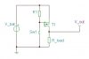
I want to power on/off a digital system using a P-channel Mosfet as shown on the attached picture.
* When the switch Sw1 is open => T1 is OFF => V_out = 0V
* When the switch Sw1 is closed => T1 is ON => V_out = V_bat

In order to minimize the consumption I'd like to use the highest pull-up resistor value. Time is not a concern for this application.

I did some hardware tests with 2 different Mosfets:
** test_#1) T1 = FDC6327C, R1 = 4M7, V_bat = 3V =>> works really good :)
** test_#2) T1 = FDG6332C, R1 = 4M7, V_bat = 3V =>> does not work. With the Sw1 open, T1 seems to be ON as V_out = V_bat. :confused:
** test_#3) T1 = FDG6332C, R1 = 220k, V_bat = 3V =>> works but consumption is too high.


Here are my questions:

q1) How to calculate the pull-up resistor value (minimum and maximum value) for a know p-mosfet ?
q2) As the 2 transistors specifications (used for test#1 and test#2) are very similar, has anyone an idea on what could be the reason of such problem.

Thank you for helping.

Stephane
 

Attachments

  • switch_P_mosfet.JPG
    switch_P_mosfet.JPG
    10.3 KB · Views: 2,753
  • FDG6332C.pdf
    93.1 KB · Views: 506
  • FDC6327C.pdf
    149 KB · Views: 346
If you dont care about switching speed, then the high value resistor will eventually turn off any enhancement mode PFET as you have drawn it. The reason that some of your PFETS do not turn on properly is because the threshold (Vt )of the PFETs you are using is on the order of three volts, and when the gate is pulled low by the switch, the Pfet doesn't turn on fully or at all...

At a supply voltage of only 3V, you are better off using a PNP transistor, or you have to buy a PFet with an unusually low Vt.
 
Last edited:
If you dont care about switching speed, then the high value resistor will eventually turn off any enhancement mode PFET as you have drawn it. The reason that some of your PFETS do not turn on properly is because the threshold (Vt )of the PFETs you are using is on the order of three volts, and when the gate is pulled low by the switch, the Pfet doesn't turn on fully or at all...

At a supply voltage of only 3V, you are better off using a PNP transistor, or you have to buy a PFet with an unusually low Vt.
Mike, I think you didn't read his post carefully:
** test_#2) T1 = FDG6332C, R1 = 4M7, V_bat = 3V =>> does not work. With the Sw1 open, T1 seems to be ON as V_out = V_bat.
Totoetsasoeur, I think your FDG6332C is defective, with excessive gate leakage. The spec says maximum leakage is 100nA. This would result in maximum Vgs of 470mV. This is less than Vgs(th) minimum of 600mV, so device should be off.

BTW, what is your load current?
 
Last edited:
Hi,

Thank you for your explanation about how to define the maximum pull-up resistor value. If I correctly understood:
R_pull_up < minimum_gate_threshold_voltage / maximum_gate_body_leakage
R_pull_up < VGS(th) / IGSSF

And for this case (from FDG6332C datasheet) :
minimum VGS(th) = 0.6V
maximum IGSSF = 100nA
Then R_pull_up < 0.6/100nA => R_pull_up < 6M :)

-------------------------
In answer to your question about load current, the final load is gonna be a uC from TI (MSP family) and a micro-motor. When uC in sleep mode, the load current is around 500nA. And when fully operational the load current is around 13mA.
But for validation, I mean for the tests (related to this post) I did so far, I used R_load = 220k => I_load = 14uA.

-------------------------
To make sure the FDG6332C are not defective, I did the test_#2 and test_#3 twice with 2 different FDG6332C. ;)
In fact, on one FDG6332C I assembled 3 small wires and pull-up resistor (4M7) directly to the device pins, and with the other one, I assembled the FDG6332C and pull-up resistor on a pcb. Then I did test_#2 and test_#3 for both cases.

Do you think I could have partially damaged both FDG6332C with a bad manipulation? I mean partially, because when using a 220k pull-up resistor both devices seem to work (test_#3). Or any other reason? :confused:

As FDG6332C package is smaller than FDC6327C, I really wish a could use the FDG6332C. This is why I keep on trying to understand the reasons of difference.

Any advice will be really appreciated.
Stephane
 
I don't have many ideas about what would be causing your problem. I would try connecting all 3 pins of the unused N-channel device to ground.
 
Status
Not open for further replies.

Latest threads

New Articles From Microcontroller Tips

Back
Top