lloydi12345
Member
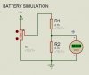
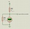
Hi, I've read that PIC16F877A can handle 5.5v. I would like to use it's ADC module. Will my circuit below be fine even if I'm using 6v Lead Acid Battery as my input source?
I would like to ask also if you have any idea what's the voltage reading that lead acid batteries are considered dead that it can't power a device fully functional.
Regards,
lloydi12345
I would like to ask also if you have any idea what's the voltage reading that lead acid batteries are considered dead that it can't power a device fully functional.
Regards,
lloydi12345
")