Continue to Site

Welcome to our site!

Electro Tech is an online community (with over 170,000 members) who enjoy talking about and building electronic circuits, projects and gadgets. To participate you need to register. Registration is free. Click here to register now.

  • Welcome to our site! Electro Tech is an online community (with over 170,000 members) who enjoy talking about and building electronic circuits, projects and gadgets. To participate you need to register. Registration is free. Click here to register now.

Making simple robot

Status
Not open for further replies.
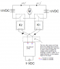
If you've ever watched battle bots or robot wars on the television, then you'll understand what this is. I'm using diodes and relays to use a small 9 volt rc circuit to power a large DC motor with two 12 VDC batteries.

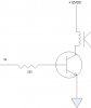
Now, the power coming out of the PFM circuit (remote control, PFM meaning Pure F**king Magic) is only two volts, ant I need more power to actually work the relays. The problem is I can't add more power to the PFM circuit because I might fry it since it's little and cheap. I remember from my "tech core" class back at my old training command (I'm a radar tech in the Navy) that transistors were a great way to amplify power, but it's been quite a while. If anyone has any advice I'd be most greatful.
 

Attachments

  • Death Machine Schematics.PNG
    Death Machine Schematics.PNG
    20.3 KB · Views: 2,193
You are going to need to use the PFM outputs to drive the gates of some MOSFETs where the source and drain of the MOSFET transistor (an NMOS specifically, just makes things easier rather than a PMOS) where the NMOS's source is connected to ground and the NMOS's drain is connected to the one end of the relay coil (The other end of the relay coil is connected to the voltage.

It is similar to using the PFM output to drive smaller relays that can be turned on by 2V but can pass larger currents that are capable of turning on your main relays.

It MIGHT work since 2V is pretty low and you would have to pick a low threshold MOSFET whose gate can be triggered with that voltage.

Add diodes in ANTI-PARALLEL with the relay coil so that the voltage spike produced by cutting off current flow through the inductance int he coil when you turn the thing off won't destroy your transistors- anti-parallel meaning in parallel with said coil, but not so current can normally flow.

Just like the transistor and motor in this schematic:


except that your PFM circuit is driving the gate instead of the 555 timer on the left, and the motor is your relay coil. THis diagram does not show the high-speed low voltage diode (like a schottky diode) that should goes in anti-parallel with the inductive load (the motor in the schematic or in your case your relay coil) to give the inductive flyback current a path to flow when cutting power to the coil, otherwise it will give the current a path to flow by producing a voltage spike until something gives.

Obviously the voltage "above and below" the drain and source of the transistor is the voltage required to turn on your relay coil, and not the voltage of needed by your motor itself (that's somewhere around the primary terminals of your relay)..
 
Last edited:
Contrary to popular belief, English is not the hardest language to learn, ROBOT is the hardest language to learn.
 
01001111.01101000.00101100.00100000.01101001.01110100.00100000.01101001.01110011.01101110.00100111.01110100.00100000.01110100.01101000.01100001.01110100.00100000.01101000.01100001.01110010.01100100.

(oh, it isnt that hard)
 
This should get you going:

Q=2N2222. Should be good up to about 100mA
 

Attachments

  • relayDrive.jpg
    relayDrive.jpg
    12.8 KB · Views: 800
Last edited:
Robot Language

01001111.01101000.00101100.00100000.01101001.01110100.00100000.01101001.01110011.01101110.00100111.01110100.00100000.01110100.01101000.01100001.01110100.00100000.01101000.01100001.01110010.01100100.

(oh, it isnt that hard)

Triode, watch your language, there might be children present!:D
 
That's a lot of 0's and one's just to say "Oh, it isn't that hard" it's not hard Binary to Text (ASCII) Conversion
010000100110010100100000011100110111010101110010011001
010010000001110100011011110010000001100100011100100110
100101101110011010110010000001111001011011110111010101
110010001000000100111101110110011000010110110001110100
01101001011011100110010100101110
 
Last edited:
If you consider that cheating you should stop using your computer and go back to using an abacus.
 
in that system yes is "011110010110010101110011" but if we were talking in bin it would probably be "1". Computers only use binary to represent ascii codes, to letters, to english when they talk to people, and they probably feel its a lot of trouble :)
 
And imagine if you could process 100 million text characters a second... How annoying it would be if you had to slow down and talk to a human!? We're obsolete, we just haven't realised yet because we're too slow. ;)

I'm sure in the future the robot overlords will find SOMETHING that us humans can still do. Maybe working in high EMI or Gamma fields or something nasty no robot would want to do itself. :)
 
the one thing we do have more of so far is memory. Technically we have a infinite amount and our brains are far more complex than anything electronic.
 
But that vast memory comes at the cost of being inexact. Our memories don't function like a recording, they are just links between things we've seen before. Equivalent to when a computer records something by creating references to things recorded elsewhere, which themselves are often made of collections of references, with only a little bit of actual data at the ends of these branches.
 
Status
Not open for further replies.

Latest threads

New Articles From Microcontroller Tips

Back
Top