Continue to Site

Welcome to our site!

Electro Tech is an online community (with over 170,000 members) who enjoy talking about and building electronic circuits, projects and gadgets. To participate you need to register. Registration is free. Click here to register now.

  • Welcome to our site! Electro Tech is an online community (with over 170,000 members) who enjoy talking about and building electronic circuits, projects and gadgets. To participate you need to register. Registration is free. Click here to register now.

Make 2 wires do the job of 3

Status
Not open for further replies.

kinarfi

Well-Known Member
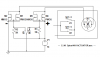
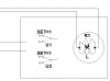
I have a linear motor that fried part of the circuit board and I am trying to modify it. It has 4 wires coming out, 2 will be for the motor driven by an external H-bridge and 2 for the end of travel switch which is 2 spdt limit switches. I have a spdt switch to choose whether the motor is extended or retracted. What I need it a method to that works as if I had 3 wire.
Any suggestions that aren't too complicated, maybe a 555 or voltage divider. As I see it, I have 3 positions, extended, retracted, and travelling.
Thanks,
Kinarfi
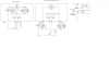
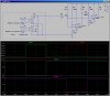
PS. The H-bridge has both NFETs turned on and both PFETs turned off because Vgs is + on all FETs and to drive the motor one way or the other, one side of the H-bridge it tied to - and the end of travel switch removes that - and only the NFETs are turned on again.
 

Attachments

  • 4X4 ACTUATOR.asc
    2.1 KB · Views: 140
  • Untitled.png
    Untitled.png
    11 KB · Views: 163
If I have understood correctly, you want to use two wires to detect the four possible states of two on/off switches.

Try this idea, it will need a few comparators but will work.

In series with each switch, connect a resistor.
Connect the switch/resisitor pairs in parallel across the two wires.
Make one resistor 2k Ohm and the second resistor 1 K Ohm.

When no switches are closed, the wires are open circuit.
When only switch #1 is closed, the resistance is 2k.
When only switch #2 is closed, the resistance is 1k.
When both switches are closed, the resistance is 0.66k.

Use this as part of a voltage divider to drive some comparators.

Job done! (Hopefully).

JimB
 
Thanks, working with your idea, just in case you assumed the end of travel switches had to wired as drawn, they can be wired any way I want.
 

Attachments

  • Untitled1.png
    Untitled1.png
    7.7 KB · Views: 157
If you take 2 12v relays, wire them in series accross the supply, then the junction of the two relay coils can go to one of your wires, connecting said wire to ground pulls in one relay, and connecting to + will pull in the other relay.
Doubling this up gives you 2 wires and 4 relays.
The issue is you need a 2 relays that when wired in series accross the supply do not pull in, some will, connecting a zener or diodes in series might do the trick.
 
How about a rudimentary DAC? Obviously, the 1mA current source is at the readout end, while the resistors reside with the two switches.
 

Attachments

  • DF75.jpg
    DF75.jpg
    194.5 KB · Views: 158
Last edited:
Still trying to figure this out, problem seems to by making it park, end of travel reached and U 2 or U 3 activated, and being able to switch U 1 and getting it to travel back and park again and then switch U 1 again and have it travel, then park.
I can get 3 different voltages across yellow and white, just need to figure out how to use that.
 

Attachments

  • Untitled1.png
    Untitled1.png
    32.9 KB · Views: 141
Here is a version that has only three states of the two switches: Both Off, S1 On, S2 On, but never S1 and S2 both on together.

I'm using two comparators to detect the three states. The outputs at "one" and "two" go low depending on which switch is closed. Load resistors R8 and R10 could be replaced with a small relay because the LM311s will sink up to 50mA.
 

Attachments

  • DF75.jpg
    DF75.jpg
    262.6 KB · Views: 150
Thanks Mike,
Kinarfi
 
Last edited:
Looks like it should work perfectly, a bit more involved than the original, but a design I will keep for when I need to do similar things. I was close, but the diode is what made the difference.
Thanks again,
Kinarfi
 

Attachments

  • 4X4 ACTUATOR.asc
    5 KB · Views: 131
  • Untitled2.png
    Untitled2.png
    26.8 KB · Views: 136
Status
Not open for further replies.

Latest threads

New Articles From Microcontroller Tips

Back
Top