Thanks The Electrician,
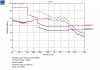
What you say is of great interest. You are absolutely right, I ran the Fourier transform on the simulator and it comes out as just over 10% at the third harmonic. I then ran a confirming LTspice simulation, and it shows the waveform being just like ours when the third harmonic is set to 10% of the fundamental.
Table 2 , Page 7 of the following…….
**broken link removed**
….shows that for Lighting equipment, the third harmonic is allowed to be no more than 2% of the fundamental input current.
This means that our 150W lighting product is a total failure on Harmonics (EN61000-3-2).
I cant understand how its set to 2% though. I mean, this is a tiny figure. The above document shows the harmonic limits being far slacker for non lighting equipment. Why is it so strict for lighting equipment?
We do have scope shots but yes the ones I have here are from the simulation.
Does anyone know why the Harmonic Limits are so ridiculously tight for Lighting Equipment?