Electro Tech is an online community (with over 170,000 members) who enjoy talking about and building electronic circuits, projects and gadgets. To participate you need to register. Registration is free. Click here to register now.
Welcome to our site! Electro Tech is an online community (with over 170,000 members) who enjoy talking about and building electronic circuits, projects and gadgets. To participate you need to register. Registration is free. Click here to register now.
The F-ram will work BUT you have to be prepared to design the control logic to drive it. What is the full story of the device that contains this counter that you need to save the contents of ? If we knew that we may be able to find a solution by a different means to saving the contents of your counter.
Yes, if he can live with a linear progression. But I don't think that a logarithmic progression (which is what's usually used for audio) could be made to work with a binary array.
I think a motorised potentiometer type volume control would be the simplest solution for the TS as it would stay in the last position selected when powered down. I can't find just the motorised potentiometer part but there are many with the control circuits on ebay.
Find many great new & used options and get the best deals for Alps 10K Slide Potentiometer Motorized N-Fader Touch Sensitive linear at the best online prices at eBay! Free delivery for many products.
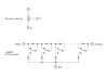
the operating principle is the one in the annex.
the switch contacts shown are those of the relays. the two resistances connected to each contact are calculated to obtain an attenuation in db.
when the outputs of the 2 binary counters are all at zero the switch contacts are all closed and all the resistors are bypassed. on the contrary when the outputs are all high, all the switch contacts are open and all the resistors are used.
This site uses cookies to help personalise content, tailor your experience and to keep you logged in if you register.
By continuing to use this site, you are consenting to our use of cookies.