Continue to Site

Welcome to our site!

Electro Tech is an online community (with over 170,000 members) who enjoy talking about and building electronic circuits, projects and gadgets. To participate you need to register. Registration is free. Click here to register now.

  • Welcome to our site! Electro Tech is an online community (with over 170,000 members) who enjoy talking about and building electronic circuits, projects and gadgets. To participate you need to register. Registration is free. Click here to register now.

LTC7803 in LTspice (Disable briefly)

Flyback

Well-Known Member
Hi,
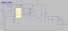
We want to disable our Buck (LTC7803) then re-enable it, and have it come back on within 1ms......the attached LTspice shows that pulling down the TRACK pin is the best way of achieving this.
Would you agree this is the best way?......Alternatively pulling the RUN pin to between 0.7V and 1.2V is the other way, but results in massive overshoot when re-enabled...would you say this is correct, as often they dont bother modelling the RUN/TRACK pins correctly in LTspice?
 

Attachments

  • LTC7803_simple_run track.zip
    2 KB · Views: 17
  • Run and track pins LTC7803.jpg
    Run and track pins LTC7803.jpg
    147.3 KB · Views: 21
Last edited:

crutschow

Well-Known Member
Most Helpful Member
as often they dont bother modelling the RUN/TRACK pins correctly in LTspice?
Why to you think that?

I would use which ever inhibit input works best in simulation.
 

Tony Stewart

Well-Known Member
Most Helpful Member
The LTC7803 regulates the VFB voltage to the lesser of 0.8V or the voltage on the TRACK/SS pin. An internal 12.5μA pull-up current source is connected to this pin.

A capacitor to ground at this pin sets the ramp time to the final regulated output voltage. The ramp time is equal to 0.65ms for every 10nF of capacitance.

---------------
You still have excess ringing on step loads due to missing phase lead compensation.
 

Flyback

Well-Known Member
Why to you think that?
Thanks, if you run that sim, you can see that having RUN voltage of 1V doesnt stop it from switching...but datasheet says it should.....LTspice sometimes doesnt bother doing all features...eg, famously, at least in the past, the SYNC pins were never modelled....so you'd put a SYNC signal in...and it'd do nothing.
 

eTech

Well-Known Member
Thanks, if you run that sim, you can see that having RUN voltage of 1V doesnt stop it from switching...but datasheet says it should.....LTspice sometimes doesnt bother doing all features...eg, famously, at least in the past, the SYNC pins were never modelled....so you'd put a SYNC signal in...and it'd do nothing.

Actually, the "RUN" pin does work.
But the simulation of that function is rather poor. If the voltage is changed to 1v, the switching stops but only after some delay, during which, the controller struggles a little trying to maintain a constant output voltage.

The "TRACK/SS" pin shouldn't be used to shutdown the output. That's not it purpose.
Its used to cacade (track) the startup of multiple controllers or, to provide slow startup of a single controller.
 

Latest threads

New Articles From Microcontroller Tips

Top